
Instruction manual

PC24E/25E
Page 9
the output of counter 1, and in the 'DOWN' position, counter 1 output is available at the output
connector, PL1 pin 4. For counter 2 to generate a hardware interrupt, it must be cascaded
with counter 1 and counter 0.
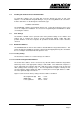
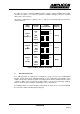
The various configurations of jumpers J10, 11 and 12 for internal interrupt generation are
shown in figure 3.
2 1 0
J10
IRQ
TIMER
UP
DN
J11 J12
2 1 0
J10
IRQ
TIMER
UP
DN
J11 J12
2 1 0
J10
IRQ
TIMER
UP
DN
J11 J12
Timer
Range
Counters
In Use
Jumper
Configuration
External
Outputs
2 µSecs
to
65 mSecs
4 µSecs
to
70 Mins
8 µSecs
to
>24 Hrs
Cntr
0
IRQ
from
Cntr 0
Ctrs
0 and 1
IRQ
from
Cntr 1
Ctrs
0, 1
and 2
IRQ
from
Cntr 2
Cntr 0
Cntr 1
None
Figure 3 CLOCK JUMPER SELECTION
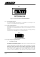
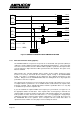
2. General Purpose Use
If no IRQ generation is required, the counter/timers can be used for any counting/timing
function, and the Clock, Gate and Output signals of each counter/timer are available on the
output connector PL1, with the exception of Counter 0 Clock, which is hard wired to the crystal
oscillator’s 1MHz source, and Counter 0 Gate, which is set at +5V (permanently enabled).
Figure 4 shows the general jumper configuration for the counter/timers.
If no IRQ generation is required, and the counter/timers are not in use, it is recommended that
the on-board oscillator is disabled by inserting J14.