
Instruction manual

PC24E/25E
Page 8
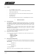
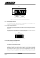
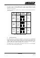
Figure 1 SW1 DIL SWITCH SELECTION OF BASE ADDRESS
2.5.2 Interrupt Request Selection
To accurately time DAC output waveforms, a programmable clock interrupts the host
computer on a selected IRQ level at the required intervals.
2.5.2.1 Jumper Setting of IRQ Level
An interrupt level must be chosen that is not otherwise used in the system. Note that unless
the interrupts are specifically supported by the software in use, the interrupt has no effect on
the PC bus.
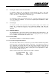
The IRQ level to be used is selected on J13. Only one level may be selected by positioning a
single jumper at the required IRQ level 2 to 7 as illustrated in figure 2.
234567
J13
IRQ
Figure 2 IRQ LEVEL SELECTION
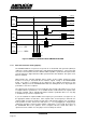
2.5.2.2 Jumper Setting of Programmable Timer
1. Generating an Interrupt
The interrupts are generated by the counter/timer QA14 which is an 82C53 and fully described
in the data sheets contained in the appendix.
A crystal oscillator provides an accurate 1MHz source which is hard wired to clock 0 input.
Jumper J10 selects the output from any one of the three possible timer outputs. These are
labeled '0' for counter 0, '1' for counter 1 and '2' for counter 2. To use counter 1, its input may
be cascaded to the output of counter 0. This is done by plugging jumper J12 in the 'UP'
position. With J12 in the 'DOWN' position, counter 0 output is directed to the output
connector, PL1 pin 16. Similarly with J11 in the 'UP' position, counter 2 input is cascaded to