
Instruction manual

PC24E/25E
Page 7
2.4 Installing the Software onto a Fixed Hard Disk
To install the software onto your hard disk, insert the diskette into drive A and select
File|Run... from the Windows Program Manager, or if you are using Windows 95 select Run...
from the Start menu. In the dialogue box that follows, type
A:\SETUP <RETURN>
The PC24E/25E software setup program will now run. Follow the instructions given on the
screen to complete the installation. See Section 4 ‘Programming the PC24E/25E’ for details
on running the software.
2.5 User Settings
The PC24E or PC25E can be operated at the factory default settings of the switches and
jumpers, but to configure the board to specific requirements without conflict with other
possible functions of the host computer, all operations described in this section should be
checked.
2.5.1 Board Base Address
The PC24E/PC25E can have its base address situated within the range 000 to FF0 hex. This
feature provides the flexibility to avoid any contention in I/O mapping that may arise and allows
the use of multiple cards fitted in the PC expansion slots.
2.5.1.1 Factory Setting
The board’s base address is set at the factory to be 300 hex.
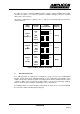
2.5.1.2 Customer Configured Base Address
The board’s base address can be selected as any sixteenth address within the range 000 to
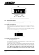
FF0 hex by means of the appropriate settings of switch SW1. This switch bank comprises a
row of eight single pole switches with each 'ON' (up) position selecting a logic 0, and each
'OFF' (down) position selecting a logic 1. The most significant hex digit is coded by the four
most left switches and the middle hex digit is coded by the four most right switches of SW1.
The least significant digit is fixed at zero.
Figure 1 below shows the factory setting of the base address at 300 hex
Most significant digit 0011 = 3 hex
Middle digit 0000 = 0 hex
Least significant Fixed = 0 hex