
Instruction manual

PC24E/25E
Page 3
PC24E AND PC25E
HIGH SPEED FOUR CHANNEL D to A CONVERTER BOARD
CONTENTS
PARAGRAPH SUBJECT PAGE
1. GENERAL INFORMATION 5
1.1 General Description 5
1.2 What the Package Contains 5
1.3 Features 6
2. USING THE PC24E/25E 6
2.1 General Information 6
2.2 Requirements to Run the Software 6
2.3 Backing up the Software Diskette 6
2.4 Installing the Software onto a Fixed Hard Disk 7
2.5 User Settings 7
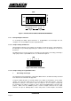
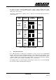
2.5.1 Board Base Address 7
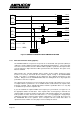
2.5.2 Interrupt Request Selection 8
2.5.3 Wait State Generator Setting (Option) 10
2.5.4 DAC Loading Mode 11
2.5.5 Voltage Output Ranges (PC24E Only) 11
2.5.6 Installing the PC24E or PC25E in the Computer 12
2.5.7 Testing the PC24E/25E 13
2.5.8 Calibrating the PC24E 13
2.5.9 Calibration Check of the PC25E 14
3. ELECTRICAL CONNECTIONS 15
3.1 User Connections 15
3.2 EMC Considerations 15
3.3 Main I/O Bus Backplane Connections 16
4. PROGRAMMING THE PC24E/25E 17
4.1 Windows DLLs and Visual Basic Example Programs 17
4.2 Turbo Pascal Demonstration DOS Program 17
4.2.1 Loading the Program 17
4.2.2 Running the Demonstrations 17
4.3 Input/Output Address Space used by the PC24E/PC25E 18
4.4 Programming the AD7548 Digital to Analog Converter 19
5. TECHNICAL SPECIFICATIONS 22
5.1 Electrical Specification 22
5.2 Physical Specification 22
6. NOTES 27