
Instruction manual

PC24E/25E
Page 10
2 1 0
J10
IRQ
OUT2
GAT2
CLK2
OUT0
GAT0
CLK0
OUT1
GAT1
CLK1
DN
UP
1MHz
+5V
DN
UP
J12
J11
J19
J17
J18
J16
J20
PL1-3
PL1-1
PL1-14
PL1-4
PL1-2
PL1-15
PL1-16
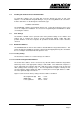
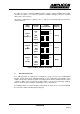
Figure 4 GENERAL PURPOSE CLOCK JUMPER SELECTION
2.5.3 Wait State Generator Setting (Option)
The PC24E/PC25E has an option to incorporate an on-board wait state generator (QA19) to
enable it to operate reliably in a wide range of PC/XT/AT and ISA machines. The need for this
is because some machines, that are otherwise IBM compatible, operate the I/O expansion bus
at clock frequencies higher than the 8 MHz specified in the ISA standard. This option is not
fitted as standard.
Many interface ICs currently available cannot operate at these higher frequencies and it
becomes necessary to slow down the bus interface signals, locally, on the PC24E/PC25E
board. The degree of retardation can be adjusted to give optimum performance in any
machine. Being local to the PC24E/PC25E board, this slowing down in no way impairs the
performance of the host computer.
The expansion bus frequency is not necessarily the same as that of the main processor clock.
A computer which is specified as a 12 or 16 MHz machine could well have an expansion bus
frequency of 8 MHz. Unless explicitly stated in the machine specification there is no easy way
to establish the speed of the expansion bus.
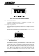
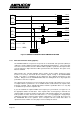
If you can establish the expansion bus clock frequency for your machine, use figure 5 to set
the appropriate number of wait states. If the expansion bus clock frequency is unknown, it is
suggested that you leave the number of wait states at the default setting of zero (No jumper).
If the operation is erratic, increase the wait states to 1, 2 or 3 by plugging in a single jumper,
until proper operation is achieved. If the number of wait states is set too high, the response of
the PC24E/25E will not be optimum. Some computers will not tolerate wait states on
expansion boards, in which case the jumper J15 must always be left out.