
Installation Manual


www.amp-research.com
11/12
IM75154 rev 02.24.15
A M P R E S E A R C H P O W E R S T E P
T M
– C H E V R O L E T / G M C
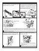
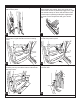
On each side of the vehicle measure from the front
edge of door line on the pinch weld to the specified
lengths below. Measure at 23” for front LED Light
and 63” for rear LED Light.
2
1
3
Remove door latch cable from door panel.
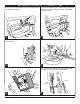
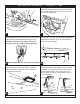
Route trigger wire into the door. Poke hole through
rubber grommet and push wire through. Pull back
door weather guard and run wire across rear door
panel to door switch plug.
Using supplied Posi-Tap connector connect trigger
wire to dark grey with white stripe wire on door switch
plug. Passenger side shares the same color wire.
Note:Wire is located in the upper outer pin of
plug. (Left on Driver, Right on Passenger Side)
Repeat steps 32-37 for door panel reassembly.
23
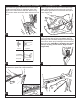
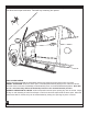
Using supplied butt connectors, connect the lamp
wires. Red to Red, Black to Black. Once Crimped
use heat gun to shrink tube. Close and wrap con-
duit with electrical tape. Secure all loose wires
with cable ties. Pull lamp wires upward to avoid
any wire snagging.
Affix lamp to rocker panel surface. Make sure the
lamp is affixed to a clean, flat surface. There is a
step down midway across the surface. Affix lamp
just outside of step down.
22
25
29
39
36
37
38
40
41