
User's Manual

Date: 2010/02/04
Version: 1.0
Status: Released
20/22 ACM8068 HW Application Manual V1.0 ©Copyright 2010, AMOD Technology
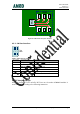
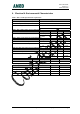
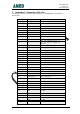
7. Appendix 1. Summary of Pin Out
The board to board connection pin definitions of ACM8068 are described as
below table:
1 Debug_RX UART1
2 Debug_TX UART1
3 RXD UART0 RX
4 TXD UART0 TX
5 Status Status indicator
6 SIMDATA SIM interface
7 SIMCLK SIM interface
8 SIMREST SIM interface
9 VSIM SIM interface
10 KBROW0
11 RI
Ring tone indicator output, can
also be used as GPIO or
interru
p
t.
12 ON_KEY
13 GPIO General purpose I/O
14 GPIO General purpose I/O
15 BACKUP
16 GPIO General purpose I/O
17 GND Ground
18 MIC2P Mic2 in positive
19 MIC2N Mic2 in negative
20 MIC1N Mic1 in negative
21 MIC1P Mic1 in positive
22 EAR+ Audio output 1 positive
23 EAR- Audio output 1 negative
24 AGND
25 AUDIOOUT- AUX out negative
26 AUDIOOUT+ AUX out positive
27 TEMP_BAT
28 VCHG
29 AUXADC
30 GND Ground
31 GND Ground
32 GND Ground
33 ANTENNA Antenna trace pad
34 GND Ground
35 GND Ground
36 GND Ground
37 GND Ground