Safety Instructions Pgs. iii-vi Installation Instructions Pgs. 6-10 Operating Instructions Pgs. 11-20 Maintenance Instructions Pgs. 20-21 READ these instructions before placing unit in service. KEEP these and other materials delivered with the unit in a binder near the machine for ease of reference by supervisors and operators. 1601 J. P. Hennessy Drive, LaVergne, TN USA 37086-3565 615/641-7533 800/688-6359 HENNESSY INDUSTRIES INC.
Contents Table of Contents Owner’s Responsibility . . . . . . . . . . . . . . . .iii Definitions of Hazard Levels . . . . . . . . . . . . . . . . .iii Warning Instructions . . . . . . . . . . . . . . . . . . . . . . .iv Safety Notices and Decals . . . . . . . . . . . . . . . . . . .v Important Safety Instructions . . . . . . . . . . . vi Before You Begin . . . . . . . . . . . . . . . . . . . . . . 1 Receiving . . . . . . . . . . . . . . . . . . . . . . . . . . . . . . . .1 Electrical Requirements . . . . .
Safety Owner’s Responsibility To maintain machine and user safety, the responsibility of the owner is to read and follow these instructions: • Follow all installation instructions. • Make sure installation conforms to all applicable Local, State, and Federal Codes, Rules, and Regulations; such as State and Federal OSHA Regulations and Electrical Codes. • Carefully check the unit for correct initial function. • Read and follow the safety instructions. Keep them readily available for machine operators.
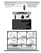
Safety Warning Instructions 1. This equipment incorporates parts such as snap switches, receptacles, and the like, which tend to produce arcs or sparks. Therefore, when located in a service facility, the unit should be in a room or enclosure provided for the purpose, or should be at least 18 inches (457 mm) or more above floor to minimize the risk of igniting fuel vapors. 2.
Safety Safety Notices and Decals For your safety, and the safety of others, read and understand all of the safety notices and decals included here and on the unit. Read entire manual before installing, operating, or servicing this equipment.
IMPORTANT SAFETY INSTRUCTIONS Before operating the lathe, review the warning information on the lathe and the cautions, warnings and dangers in this manual. Also review the following general safety instructions. Failure to follow safety instructions could result in personal injury to operator or bystanders and damage to the lathe or personal property. READ ALL INSTRUCTIONS When using your portable garage equipment, basic safety precautions should always be followed, including the following: 14.
On-The-Vehicle Before You Begin The AMMCO® 800 On-The-Vehicle Brake Lathe is intended to resurface the disc brake rotors on passenger cars, RV, and up through 1-ton trucks. Using this lathe for other purposes could result in personal injury and/or equipment damage; therefore no attempt will be made to identify all uses for which this lathe is not intended. Receiving 1.0 The shipment should be thoroughly inspected as soon as it is received.
On-The-Vehicle Features • Axial (spindle) Runout Compensation Ability while Lathe is in Motion • Semi-automatic Operation • Automatic Safety and Shut Down Systems • Operational Status Light System Specifications Maximum/Minimum Rotor Thickness 1.62 inches (41 MM) Maximum/Minimum Rotor Diameter 13.
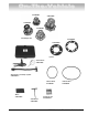
On-The-Vehicle Standard Accessories P/N 940894 P/N 940897 P/N 940896 P/N 940895 Hub Adapter Set P/N 940960 P/N 940959 Spacers Dial Indicator P/N 941063 Dial Indicator and Clamp System P/N 940961-1 Silencer Band P/N 906921 Mirror P/N 940916 Hex Wrench P/N 940915 Silencer Band P/N 906922 Carbide Inserts P/N 9076816 AMMCO 800 On-The-Vehicle Brake Lathe • 3
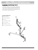
On-The-Vehicle Principal Operating Parts Know Your Unit Compare these illustrations with the unit before placing it into service. Maximum performance and safety will be obtained only when all persons using the unit are fully trained in its parts and operation. Each user should learn the function and location of all controls. Prevent accidents and injuries by ensuring the unit is properly installed, operated, and maintained.
On-The-Vehicle 800 On-The-Vehicle Brake Lathe Runout Adjustment Head Lathe Body Adjustment Knobs (red and blue) Feed Engagement Knob (gray) Carbide Inserts Feed Handwheel Insert Holders Transmission Oil Filler Plug Tool Holders Drawbar Star Knob (black) Tool Holder Locking Levers Lock Pin (yellow) Insert Adjustment Knobs Status Lights Cutting Head Assembly Control Box Dial Indicator Target Twis
On-The-Vehicle Installation and Set Up Instructions 3.3 Retrieve the four hub adapters and place each in the hub adapter set holder on the portable stand system. 800 Brake Lathe and Portable Stand System Assembly 3.0 Insert the counter balance cylinder shaft into the three leg trolley and tighten screw. 3.4 Place the chip tray over the pivot located on the cutting head assembly. 3.
On-The-Vehicle 3.6 Remove the valve cap from the valve on the counter balance cylinder. Using shop air (minimum 120 PSI) fill the cylinder to its fully extended height. 800 Brake Lathe and Portable Stand System Inspection 4.0 Note the location of pivot points for rotation. WARNING Do not exceed 140 PSI of air when filling the counter balance cylinder. WARNING Do not stand over the 800 brake lathe and/or portable stand system when pressurizing the counter balance cylinder.
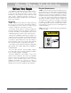
On-The-Vehicle 4.2 If adjustment is required, use the T-handle hex wrench to position the tool holders. 5.1 Note the various lights on the control box; these indicate a lathe status. 4.3 If the carbide inserts are damaged, rotate the entire lathe upside down. This provides easy access to replace or rotate the carbide inserts. Note: Carbide inserts are mounted upside-down in the insert holders. 5.2 Before switching the power on, disengage the runout adjustment head by pulling out the lock pin (yellow).
On-The-Vehicle 5.4 Now practice using the feed handwheel for overtravel status. Rotate the feed handwheel until the overtravel switch is engaged causing the 800 brake lathe to shut down. Observe that the OVERTRAVEL light status is now red on the control box. 5.10 Lock the runout adjustment head using the lock pin (yellow). It may be necessary to rotate the runout adjustment head, using the motor handwheel, to engage the lock. 5.11 Turn the power ON and observe the control box status lights. 5.
On-The-Vehicle Dial Indicator Assembly and Set Up The dial indicator set consist of three major parts: 1. Vise Grip Pliers w/Swivel Joint 2. Flex Bar Assembly 3. Indicator Assembly Clamp Screw Indicator Assembly Vise Grip Pliers w/Swivel Joint Note: Always loosen the indicator clamp screw when repositioning the indicator, otherwise the indicator will be damaged. 3. At the end of the flex bar opposite the indicator clamp you will observe a lever with a red plastic cover.
On-The-Vehicle Operating Instructions Hub Adapter Mounting and Bearing Inspection 6.0 After the wheels of the vehicle have been removed, observe the position of the brake caliper mounting to determine which side of the vehicle will allow the 800 brake lathe to mount in the upright position. This is the side of the vehicle to resurface first. 6.3 Remove the brake caliper assembly using procedures and tools as defined by the vehicle’s manufacturer, and position it in an out of the way location.
On-The-Vehicle Brake Rotor Inspection 7.0 Before attempting any resurfacing, rotor inspection is necessary. Determine the manufacturer’s rotor specifications from an approved specification guide. 7.1 Using an AMMCO® model 2780 digital micrometer (p/n 902780) or other rotor-measuring tool, record the thickness of the rotor. Observe any deep scores and gouges, as this depth will also need to be recorded. 7.2 Attach a dial indicator to the vehicle and record the rotor runout.
On-The-Vehicle Lathe to Vehicle Attachment 8.0 Attach a chatter band to the rotor as shown. This will help reduce any unwanted vibrations while refinishing the rotor, resulting in a better surface finish. 8.4 To attach the 800 brake lathe to the vehicle, approach the vehicle with the lathe tilted back on the portable stand system. This provides an easy engagement of the pilot nose into the hub adapter. Pilot Nose 8.
On-The-Vehicle Cutting Head Assembly Positioning 9.0 For each different vehicle, the cutting head assembly may need re-centering. The Lathe is Shown in Position 9.1 Loosen the head centering lock lever. 9.2 Position the cutting head assembly at a location so the centerline mark on the head is centered on the width of the brake rotor. Once positioned, retighten the head centering lock lever. 14 • AMMCO 800 On-The-Vehicle Brake Lathe 9.
On-The-Vehicle Adjusting the Lathe Runout 10.2 Turn the power switch ON. 10.0 At this point, the 800 brake lathe is ready to be turned on and adjusted for runout. Start this process by inserting the power cord into the twist-lock receptacle located on the end of the control box. 10.3 Correct for lathe runout by using the two adjustment knobs (red and blue) located on the runout adjustment head.
On-The-Vehicle 10.4 Turn the power switch OFF and disengage the lock pin (yellow) from the runout adjustment head to allow it to rotate with the lathe for the remainder of the refinishing process. 11.2 The cutting adjustment knobs are graduated .002-inch per tick mark. Note that the adjustment from number to number will move the carbide insert 0.004inch. Tool Holder Adjustment 11.
On-The-Vehicle The mirror maybe used to view the rear surface. Completing the Cut CAUTION For optimum results, once the automatic feed is engaged, do not disturb the lathe or stand during the cut or damage to the rotor may result. 12.0 Engage feed by pushing the feed engagement knob (gray) forward into the slots. It is located just behind the feed handwheel. The 800 brake lathe will now feed the carbide inserts outboard at the rate of .004-inch per revolution of the lathe spindle. 11.
On-The-Vehicle Removing the Lathe 13.0 After the refinishing process is complete and the cutting tips are clear of the rotor, disengage the feed engagement knob (gray). 13.3To remove the 800 brake lathe from the vehicle, loosen the adjustment knobs (red and blue) to the top position to reduce the drawbar tension. This will allow the drawbar to be loosened and withdrawn easily. 13.1 Switch the power OFF and remove the power cord from the twist-lock receptacle. 13.
On-The-Vehicle 13.5 Inspect the rotor after machining to verify that the rotor runout and thickness meet manufacturer’s specifications. 13.6 Remove the chatter band and hub adapter. Setup for Opposite Side Vehicle Rotor Resurfacing 14.0 To cut the brake rotor on the opposite side of most vehicles, the 800 brake lathe most be rotated to its inverted position. To invert the lathe loosen the pivot-locking lever on the portable stand system.
On-The-Vehicle 14.3 Attach runout indicator to the vehicle wheel suspension, turn on the 800 brake lathe, and make the runout adjustment required in the same manner as previously described in section 10.3 on page 15. Preventive Maintenance Oiling 15.0 The lathe is shipped from the factory with the correct amount and type of oil. Refill as necessary with EP-80-90 gear oil and check the oil level periodically. Drain the oil annually and refill to the proper level with clean EP-80-90 gear oil.
On-The-Vehicle Adjustment Knob Repositioning 16.6 Rotate the runout adjustment head back over to make the adjustment knobs accessible. At some point in the machines life you need to reposition the runout adjustment knobs. This eliminates the initial swing of the dial indicator from exceeding a full revolution. If the swing does exceed a full revolution it becomes confusing to adjust for runout. It means the adjustment knobs have to be turned down extremely far to compensate for runout.
940786 03 11/02 © Copyright 2001 Hennessy Industries All Rights Reserved Printed in USA