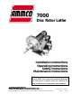
7000 ® Disc Rotor Lathe Installation Operating Safety Maintenance Instructions Instructions Instructions Instructions READ these instructions before placing unit in service. KEEP these and other materials delivered with the unit in a binder near the machine for ease of reference by supervisors and operators. 1601 J. P. Hennessy Drive, LaVergne, TN USA 37086-3565 615/641-7533 800/688-6359 HENNESSY INDUSTRIES INC. Manufacturer of AMMCO®, COATS® and BADA® Automotive Service Equipment and Tools.
Brake Lathes ii • AMMCO 7000 Brake Lathes
Contents Table of Contents Safety Notices and Decals . . . . . . . . . . . . .iv Warning . . . . . . . . . . . . . . . . . . . . . . . . . . . .iv Cautions and Dangers . . . . . . . . . . . . . . . . . . . .iv Owner’s Responsibility . . . . . . . . . . . . . . . .v Definitions of Hazard Levels . . . . . . . . . . . .v Important Safety Instructions . . . . . . . . . .vi Installation Receiving . . . . . . . . . . . . . . . . . . . . . . . . . . . . . .1 Wiring Requirements . . . . . . . . . . . . . . . . . .
Safety Safety Notices and Decals For your safety, and the safety of others, read and understand all of the safety notices and decals included here and on the unit. Read entire manual before installing, operating, or servicing this equipment. Proper maintenance and inspection is necessary for safe operation. Warning This equipment incorporates parts such as snap switches and power receptacles which tend to produce arcs or sparks.
Safety Owner’s Responsibility Definitions of Hazard Levels To maintain machine and user safety, the responsibility of the owner is to read and follow these instructions: Identify the hazard levels used in this manual with the following definitions and signal words: • Follow all installation instructions. DANGER • Make sure installation conforms to all applicable Local, State, and Federal Codes, Rules, and Regulations; such as State and Federal OSHA Regulations and Electrical Codes.
IMPORTANT SAFETY INSTRUCTIONS Before operating the lathe, review the warning information on the lathe and the cautions, warnings and dangers in this manual. Also review the following general safety instructions. Failure to follow safety instructions could result in personal injury to operator or bystanders and damage to the lathe or personal property. READ ALL INSTRUCTIONS When using your garage equipment, basic safety precautions should always be followed, including the following: 1.
Brake Lathes Installation Receiving The shipment should be thoroughly inspected as soon as it is received. The signed bill of lading is acknowledgement by the carrier of receipt in good condition of shipment covered by our invoice. If any of the goods called for on this bill of lading are shorted or damaged, do not accept them until the carrier makes a notation on the freight bill of the shorted or damaged goods. Do this for your own protection.
Brake Lathes Lathe Operation Operating Specifications Cross Feed Speed Infinitely Variable 0.002 in./rev. to 0.006 in./rev. (0.051 to 0.152 mm) Spindle Speeds: Pulley: Inner Groove Middle Groove Outer Groove Spindle Diameter 100 RPM 150 RPM 200 RPM 2-718" (73.02 mm) Capacities: Maximum Brake Rotor Diameter (3/8" Thick Rotor) Maximum Brake Rotor Diameter (1-3/4" Thick Rotor) Maximum Rotor Thickness 19-3/4" 20-1/2" 1-3/4" (44.45 mm) Maximum Arbor Load 1 Inch Standard Arbor 1.
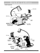
Brake Lathes Lathe Components AMMCO 7000 Brake Lathes • 3
Brake Lathes Arbor Installation The 1" arbor shipped with the lathe has been carefully matched to the lathe during final assembly and testing. Witness marks have been etched onto the arbor and spindle for repeatable, precise alignment. The witness marks should be carefully aligned when installing the arbor, Fig. B 1. A true running arbor is essential to professional quality rotor reconditioning.
Brake Lathes Cross Feed - The cross feed draws the twin tool bits across the face of a brake rotor when the cross feed drive is engaged. The cross also be operated manually using the cross feed handwheel. Feed Speed - Feed speed refers to the number of thousandths of an inch the cutting tools move across the face of the rotor per revolution of the spindle. The cross feed speed control adjusts the feed rate from .002" (.05 mm) to .004" (.10 mm) to .006" (.15 mm) per spindle revolution.
Brake Lathes Reconditioning Disc Brake Rotors Figure B7 Each brake disc should be carefully inspected for SCORING, RUST RIDGES (at the inner and outer circumference of the rotor), and HARD SPOTS. Any excessive wear or deformity should be noted and, if not within acceptable limits, the rotor should be replaced. Use a micrometer to check the thickness of the rotor at no less than three points around the circumference about 1" (25.4 mm) in from the outer diameter, Fig. B 7.
Brake Lathes Reconditioning Disc Brake Rotors—Set-Up 1. After the brake rotor is mounted on the arbor, install the silencer band. This is easily done by stretching the band to its full length and then wrapping it around the rotor and hooking the end metal loop over a lead weight, Fig. B 9. 2. Center the twin cutter to the rotor. Loosen the stud nut, Fig. B 10, and adjust the twin cutter so that the rotor is centered between the tool bits.
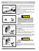
Brake Lathes 4. Adjust the drive belt to match the rotor size. Use the outer pulley groove for all passenger car and light truck rotors, Fig. B 12. Choose one of the inner grooves when machining medium duty truck rotors. 5. Make sure that the tool bits clear the rotor faces and the silencer band. Give the rotor a full turn by hand and start the lathe. Figure B12 6. Turn each tool bit control (the outer knurled knobs) clockwise until the tool bits just contact the rotor faces.
Brake Lathes The scratch will usually appear as an incomplete circle. This is caused by runout or wobble due to rotor condition or by the way the rotor is mounted on the arbor. To check that the rotor is correctly mounted, loosen the arbor nut and turn the rotor 180° by hand, (make sure the inside adapter does not rotate along with the rotor), Fig. B 15. Retighten the arbor nut. Turn the cross feed handwheel back about a half turn, start the lathe and move the tool bit in to make a second scratch cut.
Brake Lathes Machining 8. Recheck the setting of the depth-of-cut collars which were on zero. Move the tool bits inward until they just contact the faces of the rotor. Reset the collars if necessary. 9. Turn the cross feed handwheel clockwise until the tool bits are near the rotor hub, Fig. B 18. Start the lathe. Turn both tool bit controls to the desired depth-of-cut and lock them in position. Note: Either rough or finish cuts may be taken to resurface a rotor. Generally, finish cuts should be .004" (.
Brake Lathes Typical Rotor Mounting Configurations Figure B20 A B C D 1" Arbor Arbor Nut Self-Aligning Spacer Spring E F G H Large Diameter Hubless Adapter Aligning Cup Centering Cone Tapered Cone Adapter I J K L Adapter Being Used As Spacer Tapered Cone Adapter Spacer Small Diameter Hubless Adapter AMMCO 7000 Brake Lathes • 11
Brake Lathes Maintenance and Service Note: Refer to LATHE COMPONENTS. Oiling The lathe is shipped from the factory with the correct amount and type of oil. Refill as necessary with EP-80-90 gear oil and check the oil level often., Fig. C 1. Every 500 hours drain the oil and refill to the dipstick level with clean EP-80-90 gear oil. To drain the oil, remove the socket head drain plug located on the front of the lathe to the right of the cross feed assembly, Fig. C 2.
Brake Lathes Care of Arbors and Adapters CAUTION Although the adapters, arbors, and the spindle are made of top grade steel and are turned, hardened, and precision ground to close tolerances, great care should be taken in their use, handling, and storage. Even the smallest nick, scratch, or loose chip can cause incorrect rotor alignment, resulting in inaccurate machining. Remove all adapters from the arbor after machining a rotor and wipe them clean - especially the inboard adapter.
910369 02 06/01 © Copyright 1989 Hennessy Industries and AMMCO All Rights Reserved Printed in USA