Environmental Lathe Enclosure Conversion Kits Kit 940111 for 2800 to 2801 Kit 95000223 for 2800 to 2802 Kit 95000224 for 2801 to 2802 Kit 940111 Shown Safety Instructions Setup Instructions READ these instructions before placing unit in service. KEEP these and other materials delivered with the unit in a binder near the machine for ease of reference by supervisors and operators. 1601 J. P. Hennessy Drive, LaVergne, TN USA 37086-3565 615/641-7533 800/688/6359 www.ammcoats.com HENNESSY INDUSTRIES INC.
Table of Contents Important Safety instructions ................................. 3 Safety Instructions ................................................... 4 Owner’s Responsibility............................................ 4 Operator Protective Equipment ............................... 4 Definitions of Hazard Levels .................................... 4 Safety Notices and Decals ...................................... 5 Warning ...................................................................
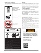
IMPORTANT SAFETY INSTRUCTIONS Before operating the lathe, review the warning information on the lathe and the cautions, warnings and dangers in this manual. Also review the following general safety instructions. Failure to follow safety instructions could result in personal injury to operator or bystanders and damage to the lathe or personal property. READ ALL INSTRUCTIONS When using your garage equipment, basic safety precautions should always be followed, including the following: 1.
Safety Instructions Owner’s Responsibility To maintain machine and user safety, the responsibility of the owner is to read and follow these instructions: • Follow all installation instructions. • Make sure installation conforms to all applicable Local, State, and Federal Codes, Rules, and Regulations; such as State, Federal OSHA Regulations and Electrical Codes. • Carefully check the unit for correct initial function. • Read and follow the safety instructions.
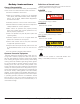
Safety Notices and Decals For your safety, and the safety of others, read and understand all of the safety notices and decals included here and on the unit. Read entire manual before installing, operating, or servicing this equipment. Proper maintenance and inspection is necessary for safe operation. Warning This equipment incorporates parts such as snap switches and power receptacles which tend to produce arcs or sparks.
Before You Begin Set-up Receiving The shipment should be thoroughly inspected as soon as it is received. The signed bill of lading is acknowledgement by the carrier of receipt in good condition of shipment covered by our invoice. If any of the goods called for on this bill of lading are shorted or damaged, do not accept them until the carrier makes a notation on the freight bill of the shorted or damaged goods. Do this for your own protection.
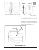
940111 & 95000223 Kits Only 940111 Kit Only Attach switch magnets to the upper strut bracket using the plastic screw and steel nut as shown. Do not tighten nut. Drill 7/8-inch diameter hole at location shown for emergency stop switch. Attach STOP decal to hood with decal hole centered over the hole in the hood. Feed the stop switch wire from outside hood through the round stop decal and hole in the hood. Slide the switch nut over the wire and tighten to the back of the switch.
940111 Kit Only Drill four 5/32-inch diameter holes at location shown to attach reed-style hood switch. Attach switch with #4 screws, washers, and nuts. Secure wire with tie wrap through the two holes as shown. 8• Drill two 5/16-inch diameter holes at location shown to attach the electrical box assembly. Use two 1/4-inch bolts, nuts, and washers to fasten assembly to the back of the enclosure. Important: Always read and follow operating instructions.
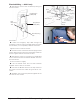
Electrical Wiring — 940111 only Receptacle Black 1. Remove the cover on the round box by taking out the two screws. Relay White Black Hood Switch Cable (Ref) Hood Switch Black Switch White White Black Foot Switch Box Mounting Tab Stop Black Green Green Wire White Stop Switch Cable (Ref) Green Screw Supplied with Round Box Ground Lug Detail 04" Round Outlet Box Power Cord Box Mounting Tab Black Electrical Box 2.
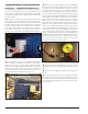
Installation Instructions Installation — 95000223 & 95000224 Kits 1. (95000224 Kit Only) Remove the foot switch cable from the old electrical box so it can be wired into the new system. Remove the old electrical box assembly along with the hood switch. These will not be used with the new system. 2. Position the control box on the back of the enclosure as shown in picture below; with the edge of the box approximately 15-inches from the center of the fan and 10-inches down from the hinge center line.
Attach Hood Switch To Enclosure Attach switch to “L” bracket and align with “Z” bracket. Drill two 0.203-inch diameter holes thru the enclosure base. Attach bracket to base. Use washers, if needed, under switch bracket to align the switch halves. Route cable along the rear of the enclosure to the control box. Secure cable with cable ties and adhesive mounting pads as required. 8. Use the provided cable ties and attachment pads as needed to fasten the wires. 9.
940113 01 10/12 © Copyright 1998 Hennessy Industries and COATS All Rights Reserved