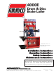
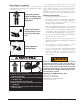
4000E Drum & Disc Brake Lathe ® * Brake lathe shown on bench with sign, toolboard and accessories. Installation Operating Safety Maintenance Instructions Instructions Instructions Instructions READ these instructions before placing unit in service. KEEP these and other materials delivered with the unit in a binder near the machine for ease of reference by supervisors and operators. 1601 J. P. Hennessy Drive, LaVergne, TN USA 37086-3565 615/641-7533 800/688-6359 HENNESSY INDUSTRIES INC.
IMPORTANT SAFETY INSTRUCTIONS Before operating the lathe, review the warning information on the lathe and the cautions, warnings and dangers in this manual. Also review the following general safety instructions. Failure to follow safety instructions could result in personal injury to operator or bystanders and damage to the lathe or personal property. READ ALL INSTRUCTIONS When using your garage equipment, basic safety precautions should always be followed, including the following: 1.
Table of Contents Important Safety Instructions . . . . . . . . . . . .ii Owner’s Responsibility . . . . . . . . . . . . . . . . . . . . .2 Definitions of Hazard Levels . . . . . . . . . . . . . . . . .2 Safety Notices and Decals . . . . . . . . . . . . . . . . . . .3 Cautions and Dangers . . . . . . . . . . . . . . . . . . . . . .3 Principle Operating Parts . . . . . . . . . . . . . . . .4 Know Your Unit . . . . . . . . . . . . . . . . . . . . . . . . . . .4 Basic Operation . . . . . . . . . . . . . . .
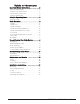
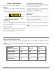
Owner’s Responsibility Definitions of Hazard Levels To maintain machine and user safety, the responsibility of the owner is to read and follow these instructions: Identify the hazard levels used in this manual with the following definitions and signal words: • Follow all installation instructions and make sure installation conforms to all applicable Local, State, and Federal OSHA Regulations and Electrical Codes. • Carefully check the unit for correct initial function.
Safety Notices and Decals For your safety, and the safety of others, read and understand all of the safety notices and decals included here and on the unit. Read entire manual before installing, operating, or servicing this equipment. Proper maintenance and inspection is necessary for safe operation. This equipment incorporates parts such as snap switches and power receptacles which tend to produce arcs or sparks.
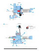
Principal Operating Parts Know Your Unit Compare this illustration with the unit before placing it into service. Maximum performance and safety will be obtained only when all persons using the unit are fully trained in its parts and operation. Each user should learn the function and location, of all controls. Prevent accidents and injuries by ensuring the unit is properly installed, operated and maintained.
Top View Not Shown Front View ✓ Do It Now! Now is a good time to fill out the Owner’s Registry Card.
Basic Operation To completely understand drum and rotor turning you must have a knowledge of the lathe itself. Spindle The spindle is a motor driven shaft that turns the arbor upon which the brake drum or rotor is mounted. By turning the drum and holding a cutting tool against the inner braking surface, metal can be removed. CAUTION Spindle Speed and Adjustment Spindle speed is measured in RPM (revolutions per minute) and is adjustable using the 3-position speed lever at the front of the machine.
Cross Feed Handwheel & Feed Lever Twin Cutter Clockwise rotation of the cross feed handwheel moves the cutting tool in towards the lathe. A twin cutter tool is used on to recondition both surfaces of a brake rotor at the same time. The twin cutter replaces the boring bar on top of the cross feed after removing the upper and lower tool bar clamps. Counterclockwise rotation of the cross feed handwheel moves the cutting tool away from the lathe. Engaging the feed lever completes the feed cycle. 1.
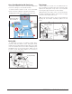
Reconditioning Disc Brake Rotors Preparation 1. Inspect the rotor carefully for scoring, rust ridges (at the inner and outer circumference of the rotor), and hard spots. Any excessive wear or deformity should be noted and, if not within acceptable limits, the rotor should be replaced. 2. Use a micrometer to check the thickness of the rotor at no less than 3 points around the circumference about 1” (2.54 mm) in from the outer diameter.
Rotor Mounting Review the descriptions of mounting drums on page 13. The same directions apply when mounting a brake rotor. Hubbed rotors are mounted on adapters that fit into the bearing races. Hubless rotors use a cone in the center hole and a hubless adapter on each side of the rotor. Spacers are used to fill out the arbor shaft so that the arbor nut can be tightened.
Double Chuck Adapter Set Up and Reconditioning Rotors Mounting drums or rotors using the Ammco double chuck adapter. 1. Install a silencer band on the mounted rotor. Stretch the band around the rotor and hook the metal loop over a lead weight. Silencer band Figure 6 – Double Chuck Adapter 1. Thoroughly clean the surface of the rotor or drum that will be mounted on the double chuck. 2. Place the hubless rotor or drum on a flat clean surface.
3. Install the safety shield. Review the cautions and dangers section and the general safety information at the beginning of this manual. The safety shield is easily screwed onto the twin cutter in the threaded mounting hole provided. WARNING Always wear safety glasses or a face shield. Cutting or grinding on an exposed surface such as a rotor will produce flying chips and debris. 6. Turn the lathe ON. 7.
11. If you see excessive runout on the rotor: A. Check rotor mounting by loosening the arbor nut and turning the rotor 180° by hand on the arbor. Make sure the inside adapter does not rotate along with the rotor. Then retighten the arbor nut, turn the cross feed handwheel back 1/2 turn, turn the lathe ON, and repeat step 10 to make a second scratch cut. Rotate rotor only 180° C. If the scratch cuts are opposite one another (180°), the rotor may not be properly mounted on the arbor.
Reconditioning Brake Drums Hubbed Brake Drums K D Preparation 1. Measure the diameter of the brake drum with a brake drum micrometer. Arrows for reading scale L Dial F A C B Figure 16 – Measure drum diameter 2. Determine if the drum will be within maximum rebore limits after reconditioning. Tapered cone adapters fit in the bearing seats, making contact near the middle of the bearing race whenever possible rather than near an edge.
5. Position the boring bar by loosening the boring bar clamp nut and sliding the boring bar inward toward the drum until the tool bit is close to the drum. This setting will be the reference used to help determine the drum recondition diameter. The boring bar position is changed whenever a drum of different diameter is machined. The entire boring bar clamp may also be swiveled to achieve the best cutting position. Dial Lock Screw Figure 21 – Set drum diameter measurement 10.
. Advance the tool bit into the bottom of the groove by rotating the cross feed handwheel counterclockwise. Note: These operations may be done with the lathe running. 21. Set the feed shut-off by sliding it on the shaft to a point that approximately equals the depth of the drum and tightening it in place. The feed will stop when it reaches this point. The depth of cut dial will show the approximate reconditioned diameter of the drum. This measurement must be compared with: Shut-off Collar A.
Maintenance and Service Grease the lead screw drive monthly. Locate the lead screw drive by pulling the protective boot back. Oiling The lathe is shipped from the factory with the correct amount and type of oil. Check oil level frequently, and refill as necessary with EP-80-90 gear oil. Dipstick Oil level Feed mechanism lead screw Grease fitting for cross feed Figure 28 – Lead screw drive Oil exposed metal parts periodically to prevent rust.
Installation Instructions Receiving The shipment should be thoroughly inspected as soon as it is received. The signed bill of lading is acknowledgement by the carrier of receipt in good condition of shipment covered by our invoice. If any of the goods called for on this bill of lading are shorted or damaged, do not accept them until the carrier makes a notation on the freight bill of the shorted or damaged goods. Do this for your own protection.
95000103 01 04/08 © Copyright 2007 Hennessy Industries and AMMCO All Rights Reserved Printed in USA