
User Manual


CONNEX
TM
User Guide
22
Connecting the Telemetry Port
The following describes how to connect the Air Unit Telemetry port to the aircraft’s flight
controller so that the Ground Unit monitor can display information received from the
aircraft’s flight controller overlaid on the video, such as flight mode, number of connected
GPS satellites, speed, height, orientation and more.
To connect the Telemetry port:
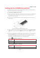
1 Connect the Air Unit Telemetry port to the aircraft using the provided Air Unit
Telemetry cable (Figure 7).
The right side of this cable goes into the Air Unit Telemetry port (Figure 2).
The left side of this cable goes into the Telemetry port of the flight controller on the
aircraft.
Figure 23: Connecting the Air Unit Telemetry Cable – Box 6
Note: Not all flight controllers are supported. You may refer to
Appendix B
on page 47 for a
list of the supported flight controllers.
Placement Guidelines – Air Unit Cable Antennas
The following describes the mandatory requirements and the best practices for optional
placement of the Air Unit vertical cable antennas.
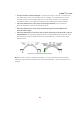
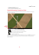
Antennas Must Face the Ground: Both Air Unit cable antennas must be placed on
the aircraft so that the antennas are pointing to the ground (vertical) when the aircraft
is in flight. For example, as shown below:
Figure 24: Antennas Must Be Placed so That They Point to the Ground
Avoid Obstacles between the Antennas and the Ground Unit: Place the Air Unit
cable antennas as low as possible on the aircraft in order to avoid line of sight obstacles
between the antennas and the Ground Unit while the aircraft is flying.
Avoid Interference: Place the Air Unit cable antennas as far away as possible from
other transceiver devices on the aircraft, especially from a transmitter in the 5 GHz
band.
Vertical Antenna
Vertical Antenna