Installation Instructions Light-duty Monitor Arm (LMA) w w w . a m i c o .
Preface IMPORTANT, PLEASE READ CAREFULLY Thank you for your purchase with Amico Accessories Inc. This unit is designed for long lasting performance, provided that the end user complies with assembly and maintenance procedures. This Instruction Manual is your guide to ensure that you get the best performance out of the equipment. Amico Accessories Inc.
Contents Section 1: Product Specifications 4 Section 2: Installation Preparation 5 Section 3: Installation on Mounting Platform Mounting to MRS (Monitor Rail System) Mounting to VRS (Vertical Rail System) Mounting on the Wall Mounting on the Desk: Clamp Mount Assembly Mounting on the Desk: Over Existing Grommet 6 7 8 9-10 10-11 Section 4: Device Installation Device Configuration Recommendations Cable Management 12 13 Section 5: Adjustments 14 Section 6: Maintenance And Troubleshooting Preventive M
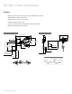
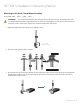
SECTION 1: Product Specifications Features • Ideal for applications where only occasional adjustment is needed • Available with or without extension • Ideal for monitors 8-17 lbs (3.6-7.7 kg) • Cable management made easy • Screens can be mounted in landscape or portrait orientation • Multiple mounting options available EXTENDED POSITION FOLDED POSITION EXTENDED POSITION FOLDED POSITION 4" [10.16 cm] 24" [60.96 cm] 16" [40.64 cm] 3" [7.62 cm] 7" [17.78 cm] 1" [2.54 cm] 11" [27.94 cm] L= 13" [33.
SECTION 2: Installation Preparation Installation, Tools and Part Requirements • HEX key sizes: 2.5 mm; 1/8" (3.2 mm), 5 mm; 6 mm • Philips Head Screwdriver size: #3 • 1/2" (12.7 mm) Socket wrench WARNING It is the installer’s responsibility to ensure all components are properly assembled and installed using the provided instruction manual. WARNING Using improperly sized screws may damage your display. If spacers are required, be sure to use correctly sized screws.
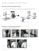
SECTION 3: Installation on Mounting Platform Mounting to MRS (Monitor Rail System): 1. Assemble LMA to X-LMA-(MON/MON-B)-ADA by placing LMA onto X-LMA-(MON/MON-B)-ADA and securing with the screw through washer, X-LMA-(MON/MON-B)-ADA, LMA, and into cap, using #3 Philips head screwdriver (as shown in the figure on the left below). PROJECT 394 PROJECT 394 CUSTOMER 2. Slide X-LMA-(MON/MON-B)-ADA into the MRS rail (as shown in the figure on the right below).
SECTION 3: Installation on Mounting Platform Mounting to VRS (Vertical Rail System): 1. Assemble LMA to X-LMA-(VRS/VRS-B)-ADA by placing LMA onto X-LMA-(VRS/VRS-B)-ADA and securing with the screw through washer, X-LMA-(VRS/VRS-B)-ADA, LMA, and into cap, using #3 Philips head screwdriver (as shown in Figure 2 below). PROJECT 394 FOR USE WITH: LMA-__-(MON/MON-B)-__, LMA-__-(VRS/VRS-B)-__ 2. Turn two X-GTA-KNOB-X-GTA-KNOB-B to loosen two HR-CONV-PIN. Tilt and guide the two HR-CONV-PIN into the 1.
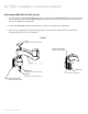
SECTION 3: Installation on Mounting Platform Mounting on the Wall 1. Drill a 1/2" (12.7 mm) hole at the desired mounting height. Hold metal channel of H-SNPTOG-1420 flat alongside plastic straps and slide channel through hole. Minimum clearance behind the wall is 1-7/8" (47.6 mm). See Figure 4.1. 2. Hold ends of straps between thumb and forefinger and pull toward you until channel rests flush behind the wall. Slide plastic cap along straps with other hand until flange of cap is flush with the wall.
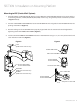
SECTION 3: Installation on Mounting Platform Mounting on the Desk: Clamp Mount Assembly For Use With: LMA-__-DSK-L-__/LMA-__-DSK-S-__ WARNING It is recommended that the desk clamp be clamped to the side or rear of desktop surface. This assembly is suitable for square edged desks only. It is the user’s responsibility to make sure the desk structure to which this clamp is attached can support the combined weight of all components. 1. Adjust the height of the desk clamp to suit desktop surface. 0.39'' - 2.
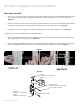
SECTION 3: Installation on Mounting Platform Mounting on the Desk: Clamp Mount Assembly pressure plate 4. Loosen the collar and adjust the height as desired before installing and tightening the Light Monitor Arm. 2.5 mm HEX key Mounting on the Desk: Over Existing Grommet 1. Remove six screws from the existing plate. 2. Secure the grommet plate to the base plate with four screws as shown below. Grommet Plate Base Plate 10 Amico Accessories Inc.
SECTION 3: Installation on Mounting Platform Mounting on the Desk: Over Existing Grommet 3. Remove the screw from the gripping plate as shown below. 4. Insert the gripping plate into bolt and tighten into base plate as shown below. Base Plate Gripping Plate 5. Unscrew the pressure plate and bolt from the base and sandwich desktop surface as shown. Turn and tighten by hand to ensure that the grommet clamp pressure plate fully contacts the desktop surface and is secure. pressure plate 6.
SECTION 4: Device Installation Device Configuration Recommendations 1. Determine the monitor configuration and if spacers are required. The monitor configuration will be either VESA 75 (75 mm x 75 mm M4 thread) or VESA 100 (100 mm x 100 mm M4 threads). 2. For VESA 100 configuration: two M4 screws are partially threaded into the top two holes at the back of the monitor. The monitor can then be hung up on the X-FIT-VSA-PLT through the two slots at the top.
SECTION 4: Device Installation Cable Management www.amico.
SECTION 5: Adjustments Adjustment Procedure 1 1. Adjust the screw clockwise for heavier loads and counter-clockwise for lighter loads for counterbalance as shown in the detailed view below, with a 5 mm HEX key. 2. Tighten or loosen the appropriate screw as shown below to adjust the monitor’s position accordingly. For swivelling, use a 5 mm HEX key. For tilting, use a 6 mm HEX key. WARNING Do not loosen top screw. Doing so may cause the head assembly to fall off.
SECTION 6: Maintenance and Troubleshooting Preventive Maintenance WARNING LMA requires periodic inspection and maintenance to perform optimally and achieve maximum operation life. WARNING The intervals shown are recommended. Maintenance schedules should be more frequent for higher use areas. Area Period (Month) Maintenance VESA Adapter 1 • Check if the adapter plate and the monitor are securely attached. Ensure the four screws on the mounting plate(s) are fastened to the tightest possible position.
SECTION 6: Maintenance and Troubleshooting Cleaning WARNING: The cleaning chemicals and methods below are not meant for controlling any infections. It shall be the responsibility of the hospital or the hospital’s infection control officer to sanitize the equipment. WARNING: Please do not spray any chemical directly onto the arm. Apply onto a soft cloth and wipe clean to prevent chemicals getting into the internal components of the arm.
SECTION 7: Product Classification LMA - - -01 01 With 7" (177.8 mm) Extension 02 Without Extension DSK-S Grommet/Desk Clamp Mount, Short 6" (152.4 mm) DSK-L Grommet/Desk Clamp Mount, Long 13" (330 mm) WAL Direct Wall Mount MON Monitor Channel VRS Amico Vertical Direct Mount www.amico.
Accessories Warranty Policy Amico Accessories Inc. warrants all mounting accessories to be free from defects in material and workmanship for a period of twelve (12) months from the date of shipment. Within this period Amico Accessories Inc. will repair or replace any part which is proven to be defective. Amico Accessories Inc. will warrant its materials to be free from defect for an additional period of four (4) years, five (5) years from the date of shipment. Within this period, Amico Accessories Inc.
Notes www.amico.
www.amico.com Amico Accessories Inc. | www.amico.com 85 Fulton Way, Richmond Hill Ontario, L4B 2N4, Canada 71 East Industry Court, Deer Park NY 11729, U.S.A. Toll Free Tel: 1.877.264.2697 Toll Free Fax: 1.866.440.4986 Tel: 905.763.7778 Fax: 905.763.8587 Email: info@amico.com AA-IM-LMA 10.16.