
Instruction Manual
22 Amico Pipeline
Manifold Switch Over
After electrical power has been applied to the manifold, the side pressurized rst is designated primary or “In Use” bank.
In order to simplify the following explanation, we will arbitrarily select right side of manifold as primary bank. The green
“In Use” LED on the right side will be illuminated and the yellow “Ready” LED on the left (secondary) bank will be illumi-
nated.
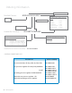
The Solenoid valve directs dome bias pressure to the bank regulator on the right side. If we use a 55psi oxygen manifold
as an example, the output of the right bank pressure regulator is approximately 155psi (100psi base pressure + 55psi
bias pressure).The output of the left bank regulator is a approximately 100psi (base pressure only, no bias pressure).
Since the bank regulator on right side has the highest pressure, all ow is supplied by right bank of cylinders.
As the cylinder pressure on the right side depletes, the pressure transducer on that side signals to the circuit board to
switch the solenoid valve. The solenoid valve then vents the dome bias pressure from the right bank regulator and di-
rects the bias pressure to the left bank regulator. The Green LED “In-use” on the right side goes out and the Red “empty” LED
illuminates, indicating a Reserve In-use alarm with the Yellow LED on left going o and the Green LED being illuminated.
When cylinders on the right side are replaced and pressure is restored, the right pressure transducer sends a signal to
the circuit board, which in turn cancels the remote switch over alarm and the Red” Empty” LED turns o and the Yellow
“ Ready” LED gets illuminated.
Since the left bank regulator has the dome bias pressure applied, its output pressure is boosted to approximately 155psi.
The right bank regulator has no dome bias pressure and its output pressure is controlled only by base pressure (100 PSI).
All ow is supplied by the left bank of cylinders until the pressure drops to approximately 120psi, the pressure transducer
sends a signal to the circuit board, causing a switch over to the right side in same fashion as previously described.
NOTE:
In the event of a power uctuation or failure, a switch over alarm will be activated on the master alarm panels.
• The solenoid valve will direct dome bias pressure to the left tank, which is the default side, if the right side is in-use.
• If the left side is in-use, the solenoid valve will continue to direct dome bias pressure until the bank depletes before
the right side takes over.
• The solenoid will not prevent the ow from being supplied no matter which side is in-use and until the system is
completely out of gas.