
Owner's manual
www.amico.com 23
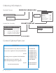
Performance Verication
Remove manifold cover.
Before beginning the test, verify following:
If the manifold is not in use, close the 3/4” source shut-o valve.
Verify that the two right-side line regulator isolation valves are open and the two left-side line regulator isolation
valves are closed.
As a starting point for this procedure, set the manifold so right bank is In-Use. If the right bank Green LED is
illuminated, proceed to the next step. If the left bank Green LED is illuminated, manually switch the manifold
to the right side by pressing the left switch on control board.
Verify that the right bank Green LED “In-use” and the left bank Yellow “Ready” lights are illuminated.
If the manifold is connected to a master alarm panel, verify the manifold switch-over alarm is not activated.
If the manifold is equipped with a pilot regulator, verify the gauge on it reads 50 PSI.
Verify gauge reading for the “In-Use” right bank regulator. If the pressure is not correct, refer to the bank regulator
pressure adjustment procedure.
Verify the line pressure gauge reading. If the pressure is not correct, refer to the line regulator pressure
adjustment procedure. Note the reading for later use.
Watch the pressure gauge readings of the right side bank regulator and the line pressure gauge for at least ve
minutes. Readings may be slightly higher without vent ow but verify the readings do not continue to increase.
Close all cylinders on the right side of the manifold. Use the bleed valve on the line regulator to “S-L-O-W-L-Y”
vent o pressure until the right bank high pressure gauge drops. Verify that the manifold switches to left bank
when the right bank high pressure gauge drops below the specied setting of the bank regulator.
Verify only the left bank Green LED “In-Use” and the right bank Red “Empty” LED illuminates.
If the manifold is connected to a master alarm panel, verify that the switchover alarm is activated.
Close the right-side line regulator ball valves and open the left line regulator ball valves.
Slightly depress the bleed valve on the left line regulator to create a small ow of gas through manifold.
Verify the pressure gauge reading on the bank “In-Use” regulator to see if it is set up as per the specied pressure
setting. If the pressure is not correct, refer to the bank regulator pressure adjustment procedure.
1.
2.
3.
4.
5.
6.
7.
8.
9.
10.
11.
12.
13.
14.
15.
16.
17.
Use the following test steps to verify the manifold’s functional performance: