Operating & Maintenance Manual Automatic Medical Gas Manifold Dome Loaded Regulator CSA w w w . a m i c o .
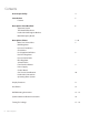
Contents User Responsibility 4 Introduction 5 Features Description of the Manifold 6 Shipment Details The Manifold Enclosure Header Bar Wall Support Bracket Manifold Display Board Description of Parts 7 - 10 Main Line Source Valve 7 Bank Regulator Pressure Transducers Check Valve Line Regulator Ball Valve 8 Dual Line Regulator Pressure Relief Valve Pilot Regulator
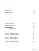
Initial Power-Up 19 - 20 Gas Flow Through the Manifold 21 Manifold Switch Over 22 Performance Verification 23 - 24 Bank Regulator Pressure Adjustment 25 Bank Regulator Replacement 26 Line Regulator Pressure Adjustment 26 Line Regulator Replacement 27 Control Board Replacement 28 Cylinder Changing Procedures 29 Ordering Information 30 - 31 Control Cabinet Part List Appendix A Manifold Internal Layout 32 Appen
Microprocessor Digital Manifold Microprocessor Digital Manifold User Responsibility USER RESPONSIBILITY USER RESPONSIBILITY The information contained in this Installation and Maintenance Manual pertains only to the Amico Automatic Gas Manifold.
Introduction The Amico Automatic Gas Manifold is designed to provide a reliable, uninterrupted supply of gas to a hospital or other medical facility. The manifold utilizes multiple high-pressure cylinders divided into two equal banks. One bank is designated as a “Primary” source of gas while the other bank stands in reserve as a “Secondary” source. A display of LED’s on the front of the manifold indicates the status of the gas supply. Each bank has a Green (IN USE), Yellow (READY) and Red (EMPTY) LED.
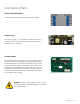
Description of the Manifold SHIPMENT DETAILS The Manifold system may be shipped in more than one carton, depending on the number of cylinder connections. The main carton contains the following items: • • • • Manifold control panel (with power supply assembly) Wall mounting bracket (attached to manifold control panel) 3/4” Source shut-off valve Installation, Operation and Service Manual Additional cartons may contain appropriate number of headers and cylinder pigtail assemblies.
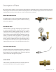
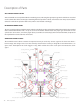
Description of Parts When replacement cylinders are attached to the depleted bank, the Red LED goes out and the Yellow LED illuminates indicating that the bank has been automatically designated as the secondary supply. No other user interaction is required. Both sets of dry contacts close to cancel any external alarm condition. MAIN LINE SOURCE VALVE An isolation valve ¾ “ with a locking handle supplied with the manifold should be installed on top of the manifold connecting to the main supply line.
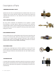
Description of Parts LINE REGULATOR BALL VALVE Quarter-turn ball valves are provided upstream and downstream of each line regulator. These valves allow for removal and servicing of one of the line regulators while the other is in use. All four ball valves are normally in the open position. DUAL LINE REGULATOR On every Amico Automatic Gas Manifold the line regulator is capable of maintaining a constant dynamic delivery of pressure at the maximum designed flow rate of the system.
Description of Parts Microprocessor Digital Manifold FRONT PANEL INDICATORS USER RESPONSIBILITY Six front panel indicators monitor the status of the manifold. The information contained in this Installation and Maintenance Manual, pertains only to the ALERT-2 microprocessor based digital manifold. This product will perform in conformity with the descriptions contained in this manual when assembled, operated, maintained and serviced in accordance with the installation instructions provided.
Description of Parts GAS SERVICE IDENTIFICATION Amico manifolds are clearly labeled for the intended gas use, indicating the appropriate gas with a label that is attached on the cabinet door. There are two pipes extending from the top of the cabinet, one is for the main line pressure and the other is the vent for the pressure relief valves, which is also labeled accordingly. HEADER BAR CONNECTIONS The gas-specific header bar should be attached to the Inlet block on either side of the manifold.
Display Functions 1. Introduce power to the control cabinet. 2. Follow Cylinder Changing Procedures on the side of the cabinet to ensure that all cylinders and fittings are secure and properly connected to the header bar. 3. Check the indicator LED for proper functioning. 4. Only one Green LED, on the side which had its operating regulator set first, should be lit and the other side should have a Yellow LED lit. 5.
Installation PRECAUTIONS • Tampering with gas specific connections shall be prohibited. Do not alter, remove or modify gas specific connections. • Keep all manifold parts, tools and work surfaces free of oil, grease and dirt. These and other flammable materials may ignite when exposed to high pressure oxygen or nitrous oxide. • Do not use chemicals, lubricants or sealants unless specified in these instructions.
Wall Mounting Instructions 1. Remove manifold control panel from the shipping carton and ensure it’s in an upright position on the foam packaging insert. 2. Using the back support bracket as a template, place on the flat wall, align top of the bracket with the level horizontal line. The vertical center line of the bracket will be the vertical center line of the installed manifold. The support bracket should be mounted 61-1/2” [1,562.
Wall Mounting Instructions 4. Hang the manifold control panel on the mounting bracket. The top two control panel mounting bolts will slide into slots of the bracket. The bottom of the manifold control panel should be angled away from the bracket until the top two bolts have been inserted as shown in Figure 2. Figure 2 NOTE: A bracket mounting height of 61-1/2” [1,562.
Wall Mounting Instructions The bottom of the control panel can then be positioned so that the holes at the bottom of the panel align with the holes in the hanging bracket. Use 3/8” [9.525 mm] bolts to secure the cabinet to the bracket as shown in Figure 3. Figure 3 Microprocessor Digital Manifold USER RESPONSIBILITY Microprocessor Digital Manifold The information contained in this Installation and Maintenance Manual, pertains only to the ALERT-2 microprocessor based digital manifold.
All Manifolds should not be repaired or altered without prior written approval by Amico Microprocessor Digital Manifold Corporation or it’s distributors. Failure to comply will void all warranty on the manifold. Statements in this manual preceded by the words WARNING, CAUTION, DANGER and NOTE are of special significance. Please read these sections carefully.
Testing for Leakage The following instructions apply for performing a leak test on the joints made during assembly and connection of the Amico manifold. The connections inside the Amico control cabinet have been inspected at the manufacturing plant and DO NOT require leak testing. In order to determine whether any leaks exist between cylinder header bar sections or at the pipeline connections, the systems must be pressurized using either oil-free dry air or oil-free dry nitrogen.
Testing for Leakage Precautions The Amico Automatic Gas Manifolds are designed in accordance with the CSA Standard. There are three categories of Amico manifolds depending upon the delivery pressure.
Initial Power-Up 1. Release the two latches on either side of the manifold control panel and remove the cover. 2. Verify the following: • Both master valves located on both header bars are turned fully counter clockwise (open). • All four line regulator isolation valves are open (handles horizontal). • Power supply has been connected. • Both Red “empty” indicators on the front of the manifold are illuminated. • If connected to a master alarm panel, “Secondary Supply” alarm is activated. 3.
Initial Power-Up 11. Verify the following: • Right bank Red “Empty” LED goes out. • Right bank Yellow “Ready” LED illuminates. • Right bank cylinder contents gauge reads cylinder pressure. 12. Close left bank cylinder. Depress valve located on the side of the line regulator. Verify the following: • Left bank cylinder contents gauge drops “S-L-O-W-L-Y”. • As left cylinder contents gauge is nearly depleted, the manifold will change over to the right bank.
Gas Flow Through the Manifold High pressure gas is provided to the left and right manifold bank inlets via cylinders, pigtails, and header assemblies. Flow of high pressure gas through the left and right side of manifold is exactly the same, each passing through a master valve located on the header and then directly to a bank regulator. Bank regulators reduce incoming cylinder pressures to an intermediate pressure. Bank regulators are referred to as a “dome loaded” type of regulator.
Manifold Switch Over After electrical power has been applied to the manifold, the side pressurized first is designated as the primary or “In Use” bank. In order to simplify the following explanation, we will arbitrarily select right side of manifold as primary bank. The Green “In Use” LED on the right side will be illuminated and the Yellow “Ready” LED on the left (secondary) bank will be illuminated. The Solenoid valve directs dome bias pressure to the bank regulator on the right side.
Performance Verification Use the following test steps to verify the manifold’s functional performance: 1. Remove manifold cover. 2. Before beginning the test, verify following: 3. If the manifold is not in use, close the 3/4” source shut-off valve. 4. Verify that the two right-side line regulator isolation valves are open and the two left-side line regulator isolation valves are closed. 5. As a starting point for this procedure, set the manifold so right bank is In-Use.
Performance Verification 18. Verify that the line pressure gauge reading is the same as in step 11. If the pressure is not correct, refer to the Line regulator pressure adjustment procedure. 19. Watch the pressure gauge readings on the left bank regulator and the supply line for at least five minutes to ensure the readings do not continue to increase. 20. Close all cylinders on the left side of the manifold. Depress the bleed valve slightly so that the left bank high pressure gauge drops “S-L-O-W-L-Y”.
Bank Regulator Pressure Adjustment This procedure should only be performed if the bank regulator pressures are not within acceptable limits during performance verification procedure or after installation of a new bank pressure regulator. Base pressure setting is a mechanical adjustment controlled by the regulator’s internal adjusting spring and without any dome bias pressure. Recommended settings are listed on page 18 in the Table under the heading of “Intermediate Pressure - Ready Bank”.
Bank Regulator Replacement Should it be necessary to replace the bank regulator, it can be done while the manifold is in service. However, this should only be done by qualified technicians experienced in servicing medical equipment. 1. Remove the two top screws at the base of the display board bracket and bend the display board assembly back for easy access to the union nuts that secures the bank regulator. (Follow label instructions) 2.
Line Regulator Replacement If necessary, the line regulator replacement can be performed while manifold is in service. However, this should only be done by qualified technicians experienced in servicing medical equipment. 1. Close the two ball valves on inlet and outlet of line regulator to be replaced. 2. Loosen union nuts on the two closed isolation valves. 3. Vent pressure from the bank, which was shut off in step 2 by depressing the bleed valve on side of the regulator. 4.
Control Board Replacement If necessary, the control board replacement can be performed while the manifold is in service. However, this should only be done by qualified technicians experienced in servicing medical equipment. 1. Remove two top screws at the base of the display board bracket and tilt the display board assembly backwards. 2. Disconnect power supply. 3. Remove the screws located on the circuit board, which detaches it from the front plate.
Cylinder Changing Procedures Microprocessor Digital Manifold 1. Keep the main bank valve open throughout these procedures. USER RESPONSIBILITY 2. Close cylinder valves on all empty cylinders. 3. Disconnect pigtails from cylinder valve outlets, using an appropriate wrench. 4. Place protective caps over the cylinder valves of the empty cylinders and move them aside. The information contained in this Installation and Maintenance Manual, pertains only to the ALERT-2 5.
Ordering Information Manifold Cabinet: M2HD-DLC-HH(H)-E-GAS DLC = Dome Loaded (CSA) E = English (CSA) F = French HH = High Pressure HHH = Heaters Header-Bar Assembly: Oxygen Nitrogen Medical Air Carbon Dioxide Nitrous Oxide = = = = = OXY NIT AIR CO2 N2O M2-HBYY-XXE-GAS The Letters “YY” Defines the Type of Header-Bar Assembly: The Letters “XX” Defines the Number of Cylinders: “TS” “TC” “XS” “XC” 2 x 2 use 04 4 x 4 use 08 = Straight c/w Stainless Pigtails = Straight c/w Copper Pigtails = Stagg
Control Cabinet Parts List DESCRIPTION Intermediate check valve for all gases Operating pressure relief valve Nitrogen Operating pressure relief valve Oxy, N2O, Air & CO2 Line Pressure relief valve for Nitrogen Line pressure relief valve for Oxy, Air & CO2 Plug & Chain assembly - Air Plug & Chain assembly - CO2 Plug & Chain assembly - N2O Plug & Chain assembly - Nit Plug & Chain assembly - Oxy Copper pigtail c/w Check valve - Air Copper pigtail c/w Check valve - CO2 Copper pigtail c/w Check valve - N2O Copp
Appendix A Manifold Internal Layout 32 Amico Pipeline
Appendix B Piping Schematic Diagram Pig-Tail Check Valve Cylinder Valve High Pressure Inlet Valve Pressure Transducer Operating Pressure Regulator Check Valve Line Pressure Regulator 2 - Way Valve Line Pressure Relief Valve Operating Pressure Relief Valve Bleed Valve Operating Pressure Gauge Pilot Regulator For Nitrogen Line Pressure Gauge VENT TO OUTSIDE VENT TO OUTSIDE TO PIPELINE DISTRIBUTION SYSTEM VENT TO OUTSIDE 10 9 9 13 14 7 7 11 8 CONTROL CABINET 6 6 12 12 4 LEFT HAND BANK CYLINDER
Appendix C Wiring Schematic Heater Units Power Supply Heater Cartridge Wires Heater Cartridge (Inside Inlet Pressure Block) Inlet Pressure Block Reset Switch Reset Switch Heater Cartridge (Inside Inlet Pressure Block) Inlet Pressure Bloc The Heaters normally switch on when the temperature drops below 24°C or 75°F. If the temperature exceeds 65-75°C or 160-175°F, the Heater re-set switch will trip and the Heaters will automatically switch off.
Appendix D Electrical Wiring Diagram Amico Medical Gas Alarm Master Alarm 115 VAC Supply Voltage Amico Gas Manifold Connect the NO loop to the appropriate points. 110 / 240 VAC Wiring 50 / 60 Hz C NO Current Draw: 1 Amp. Max. External Power Supply www.amico.
Appendix E Control Cabinet Wiring Diagram 36 Amico Pipeline
Appendix F Staggered Header Bar www.amico.
Appendix G Straight Header Bar Setup 38 Amico Pipeline
Appendix H Optional Header Bar Setup www.amico.
Appendix I Straight Header Bar Setup 40 Amico Pipeline
Notes www.amico.
Notes 42 Amico Pipeline
Notes www.amico.
www.amico.com Amico Pipeline | www.amico.com 85 Fulton Way, Richmond Hill Ontario, L4B 2N4, Canada Toll Free Tel: 1.877.264.2697 Toll Free Fax: 1.866.440.4986 Tel: 905.764.0800 Fax: 905.764.0862 Email: info@amico.com C US LISTED C APE-INSTAL-MAINT-DL-MANI 01.07.