Condor Manual Corporation
PREFACE IMPORTANT, PLEASE READ CAREFULLY Thank you for your purchase with Amico Accessories Inc. This unit is designed for long lasting performance, providing the end user complies with assembly and maintenance procedures. This Instruction Manual is your guide to ensure that you get the best performance out of the equipment.
CONTENTS Section 1: Product Specifications Features 4 5-6 Section 2: Installation Preparation Installation, Tools and Part Requirements Pre-Installation Information 7 7 7 Section 3: Installation on Wall Mounting Preparation Mounting on Wall with Studs/Backing Mounting on Hollow Wall 8 8 8 9 Section 4: Equipment Installation Equipment Mounting Recommendation Mounting of Accessories 10 10-11 12-13 Section 5: Adjustments Adjusting the Counterbalance Adjusting Inter-Accessory Distance 14 14 14 Section
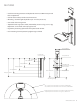
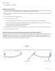
SECTION 1: Product Specifications Height: 45"/114.3 cm Width: 12"/30.5 cm Thickness: 3"/7.6 cm Vertical motion range: 17"/43.2 cm Mounting channel length: 28"/71.
FEATURES • Used for mounting monitors and keyboards on Amico SSM Arms to provide vertical adjustment • Counter-balanced to provide ease of movement • Mounting channel height adjustable up to 17 inches (43.18 cm) • Concealed cable management • Adjustable load range (10 to 30 lbs, 20 to 40 lbs) (4.5 to 13.6 kg, 9 to 18.1 kg) adjustment can be made at the top right corner. • Ergonomic positioning options for the keyboard and monitor • Lock mounting channel position by tightening Lock-knob 12.00 (30.48cm) 1.
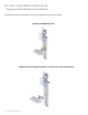
FEATURES 27.00 (68.58cm) (W/O MONITOR) 27"(68.58cm) Clearance Needed for 12" Double Arm, SSM-LCD-15 (Shown) 17"(43.18cm) Clearance Needed for 12" Single Arm, SSM-LCD-05 7"(17.78cm) Clearance Needed for Flush Mount, SSM-LCD-45 5"(12.70cm) Clearance Needed for Ultra Flush Mount, SSM-LCD-F5 2.00 (5.08cm) 43"(109.22cm) Clearance Needed for 12" Double Arm, KEYBRDF-SSM1 (Shown) 33" (83.22cm) Clearance Needed for 12" Single Arm, KEYBRDF-SSM0 23" (58.42cm) Clearance Needed for Flush Mount, KEYBRDF-SSM4 17" (43.
SECTION 2: Installation Preparation Installation, Tools and Part requirements Tools required: • Drill • Allen Key size 5/32" (0.39 cm) • Drill bit size 9/64" (0.35 cm) • Allen Key Size 1/8" (0.31cm) • Drill bit size ½"(1.27 cm) • ½" Socket Wrench (1.27 cm) • Philips screwdriver NOTE: Amico does not provide any monitor hardware, nor the tools necessary for assembly. Hardware required: • 2 X Mounting channel stopper with 10-32 screw, ½" (1.
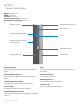
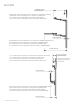
SECTION 3: Installation on Wall Mounting Preparation The Condor comes with a set of channel covers. Remove the central channel cover to expose all 7 wall mounting holes. Gas Spring Cover Cable Management Channel Cover Location of top mounting hole Mount bottom of Condor Channel 27" (2 ¼ feet) (68.58 cm) from floor, to provide a seated 28" (71.12 cm) keyboard height to standing 45" (114.3 cm) keyboard height for a single SSM Arm. Mounting distance changes to 25" (63.
SECTION 3: Installation on Wall Mounting on hollow wall: 1. Locate and mark the top mounting hole at a distance of 69"/168 cm from the floor for a configuration using single SSM arms, and 71"/180 cm from the floor for a configuration using double SSM arms. 2. Use the Condor as a template to mark the remaining mounting holes, checking to ensure the Condor is kept plumb, flush and level. 3. Drill ½ inch holes at each marked position. 4. Install snap-toggles in all 7 holes: a.
SECTION 4: EQUIPMENT INSTALLATION Equipment Mounting Recommendations The following mounting configurations are recommended for safe mounting on Condor Keyboard and Monitor Flush Monitor Flush and Keyboard with 9"/12" (22.86 cm/ 30.48 cm) SSM Arm 10 Amico Accessories Inc.
SECTION 4: EQUIPMENT INSTALLATION Equipment Mounting Recommendations Monitor on 12" (30.48 cm) SSM Arm and Keyboard on 9" x 9" (22.86 cm x 22.86 cm) SSM Arm Both Monitor and Keyboard on 9" x 9" (22.86 cm x 22.86 cm) SSM Arm It is advised to mount CPU near top left of Condor; with power and data outlets close to CPU for convenience in cable management. Consider using USB cable extensions or a USB hub if necessary for keyboard, mouse and/or scanner cables. www.amico.
MOUNTING OF ACCESSORIES Mounting of accessories to the mounting channel can be done by mounting the accessories to an adapter first. WARNING To prevent the adapter from sliding down the channel, ensure the four set screws are fastened to the tightest possible position, serious injuries could result if the set screws are not properly fastened. NOTE: Top and bottom stopper are there to prevent the adapter from sliding out of the MRS.
MOUNTING OF ACCESSORIES Mounting Channel Mounting Channel Stopper Figure 5 4. Once the accessory is at the desired height, tighten all four set screws to the tightest possible position on the adapter using 1/8" (0.3175 cm) hex key. 5. Re-install the mounting channel stoppers onto the mounting channel by attaching them to the two holes on the bottom of the channel (Figure 5). WARNING The channel stoppers will break if screw is over tightened. 6.
SECTION 5: Adjustments WARNING Do not over-rotate the counterbalance bolt. Once you feel resistance, stop. Forcing the bolt will damage the internals of the Condor and void the warranty. NOTE: Only adjust if necessary. Adjusting the Counterbalance 1. Once the Condor is securely installed, tighten the locking knob to lock the Condor. 2. To adjust for heavier loads, slowly loosen the counterbalance bolt rotating counter-clockwise, located on the top right corner of the Condor.
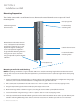
SECTION 6: Cable Management Cable Requirement for CPU Mounting on Top Cable length minimum: 10 feet (304.8 cm), maximum number of cables: 5 Cable Routing Procedure NOTE: All accessories should be mounted and properly positioned before cable management procedures. 1. Release Condor Lock and bring Condor mounting channel to top most position and re-lock. 2. Open Condor left cover (Figure 3). 3. Remove both top and bottom Channel Covers as well as both cable clamps. 4.
SECTION 7: Maintenance, Troubleshooting and Product Classification Troubleshooting Condor Mounting Channel is Drifting Upwards or Downwards Counter-balancing mechanism is not set appropriately for the given load. • Counter-balancing mechanism can be corrected by tightening or loosening the screw embedded inside the top right corner of the Condor. Turn clockwise for lighter loads and counter-clockwise for heavier loads.
SECTION 7: Maintenance, Troubleshooting and Product Classification Preventative Maintenance WARNING The Condor requires periodic inspection and maintenance to perform optimally and achieve maximum operation life. The intervals shown below are recommended. Maintenance schedules should be shortened for Condors that see heavy use. NOTE: Please follow the Preventative maintenance protocol for the accessories as stated in the manual for those accessories.
PRODUCT CLASSIFICATION AHC-1-L4-K4-C2 • Includes flush LCD SSM arm – provides tilt and swivel • Includes flush keyboard SSM arm – provides swivel and negative tilt • Folds to less than 10" (25.4 cm) from wall • Keyboard extends 23" (58.42 cm) from wall AHC-1-L0-K0-C2 • Includes 12" (30.48 cm) LCD SSM arm – provides tilt, articulation and swivel • Includes 12" (30.48 cm) keyboard SSM arm – provides swivel, articulation and negative tilt • Folds to less than 10" (25.
CLEANING WARNING WARNING The cleaning chemicals and methods below are not meant for controlling any infections. It shall be the responsibility of the hospital or the hospital’s infection control officer to sanitize the equipment. Please do not spray any chemical directly onto the arm. Apply onto a soft cloth and wipe clean to prevent chemicals getting into the internal components of the arm.
www.amico.com Amico Accessories Inc. | www.amico.com 85 Fulton Way, Richmond Hill Ontario, L4B 2N4, Canada 71 East Industry Court, Deer Park NY 11729, U.S.A Toll Free Tel: 1.877.264.2697 Toll Free Fax: 1.866.440.4986 Tel: 905.763.7778 Fax: 905.763.8587 Email: info@amico.com ACC CONDOR MANUAL 18.09.