Approval and Installation Booklet Motorized Retractable Ceiling Column w w w . a m i c o .
Table of Contents Product Description 3 Cleaning 3 Inspection and Testing 3 Range of Column Retraction 4 Device and Accessory Chart 5 Device Placement (Bottom View) 6 Electrical Diagram (Bottom View) 7 Riser Plate to Outlet Detail 8 Termination Box 9 Riser Pipe Assembly 10 Mounting of the Ceiling Column 11 Mounting Information 12 Typical Location View 13 Wiring Diagram 13 Remote (Optional) 14 Control Unit 15 - 16 Linear Drive 17 - 18 Servicing 19 *NOTE: Amico requires all
Product Description The motorized retractable ceiling column shall be an Amico Alert-1 series. The motorized retractable ceiling column shall be of the motorized operated type. The column shall consist of an upper section for rigid mounting at the ceiling level and a telescopic lower section. The lower section of the column is activated by a motorized actuator mounted into the internal shell of the column.
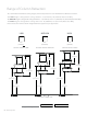
Range of Column Retraction To accommodate for different ceiling heights, Amico Corporation has standardized three different variations. The LOW height is designed for ceilings below 9’ - 0” (2743mm) 10” (254mm) Retraction Only. The MEDIUM height is designed for ceilings between 9’ - 1” (2769mm) and 9’ - 11” (3023mm) 14 “ (355.6mm) Retraction Only. The HIGH height is designed for ceilings above 10’ - 0” (3048mm) 18” (457.2mm) Retraction Only.
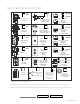
Device and Accessory Chart *QD XXX E9-RED PE E10-IVO. Ohmeda / Medaes Compatible Ceiling Column Passive Evacuation (19mm/33mm) CH XXX IMP Chemetron Compatible E11-RED E12-IVO. Passive Evacuation with Impedance Valve (19mm/22mm) (Side Mount Only) Single Receptacle 8310-HG 125V/20a (US / International) E5-RED GJ PB XXX Puritan-Bennett Compatible Duplex Receptacle 8300-HG 125V/20a (US / International) E6-IVO.
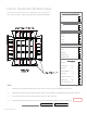
Device Placement (Bottom View) Please fill the devices that you require for your application. (Specify by using the symbols on Page 5 of this Approval Booklet.) Is a Local Switch Required? * if YES, please provide the location (ex.
Electrical Diagram (Bottom View) Circuit Chart *Please Select One of the Following: Amico recommended circuit schedule based on layout Custom circuit schedule. Please specify on circuit chart Receptacle Type: US/CAN *BRITISH (simplex only) *GERMAN (simplex only) *Please specify electrical details: NOTE: Type of wire: THHN XHHW RW90 AWG Wire Gauge: Wire Color: 10 & 12 LIVE/HOT 12 gauge Black 1. Two electrical/communication/medical gas devices cannot be placed together at any corner. 2.
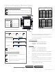
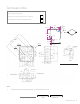
Riser Plate to Outlet Detail C - Riser Access Panel This Side Riser Plate Bottom View Looking Up 17” [431.8mm] 4.5” [114.3 mm] above finished ceiling pipe stub for column X4 For DISS riser pipe inlet (see page 9) anti-sway support (supplied by others) anti-sway support (supplied by others) 7/8” [22.2mm] hole X8 17” [431.8mm] 14.75” [374.65mm] 14.75” [374.65mm] Termination X4 X4 See page 9 box use see page 10 DISS 1.00” [25.4mm] 1.00” [25.4mm] for electrical conduit use 2A 14.75” [374.
Termination Box Is a riser mounted termination box required? See diagram below (refer to page 8 for locations). Yes (Amico provides termination box - default) No (Termination box will be supplied by others) 4.125” [104.78mm] 4 - R .344” [R 8.73mm] 0 .344” [ 0 8.74mm] .629” [15.97mm] .394” [10.02mm] 0 .188” [ 0 4.78mm] .331” [8.41mm] 4.125” [104.78mm] .376” [9.55mm] .203” [5.16mm] 2 5/8” [66.68mm] .409” [10.39mm] 4.773” [121.23mm] .061” [1.55mm] 10 - 32 TAPPED HOLE DETAIL A R 1/16” [1.
Riser Pipe Assembly CAUTION Yes (Amico provides termination box - default) No (Termination box will be supplied by others) * Before brazing the Riser an intermittent blow-out purge is required to be done until all debris are cleared from the Pipeline System. NOTE: * Installations of the Riser should be done in accordance with current NFPA 99 and CSA Z7396.1. 1. “X” represent US/ISO and GAS type i.e: C-PIPE-CHK-U-AIR 2. 3/8” [9.97mm] ID 1/2” [12.
Mounting of the Ceiling Column There will be four (4) 1/2” - 13 x 8” threaded rods attached to the riser plate. Each rod contains four (4) 1/2” nuts, four (4) 1/2” washers and four (4) nylon retaining washer. Remove the outer and inner access panels from the ceiling column. NOTE: The gas hose(s) and electrical conduit(s) have been wrapped and attached to the top of the ceiling column to maximize the smooth movement of the lower telescopic portion of the ceiling column.
Mounting Information NOTE: Riser plate to be installed in ceiling with appropriate mounting structure and anti-sway support. The methods of support shown are provided for information only. 17” Sq. [431.8mm Sq.] 14.75” Sq. [374.65mm Sq.] STRUCTURAL CEILING 9.5” Sq. [241.3mm Sq.] RISER PLATE ANTI-SWAY SUPPORT STRUCTURE (SUPPLIED BY OTHERS) 1.00” [25.4mm] 4.5” [114.3mm] 3/4” [19.5mm] or 7/8” [22.23mm] THREADED ROD (X4) (SUPPLIED BY OTHERS) FINISHED CEILING COLUMN MOUNTING PLATE MIN. 13” [330.
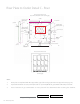
Typical Location View Access Panel Recommended location of columns in surgeries and special care areas. 3’ - 4’ 3' to 4’ [914.4 - 1219.2mm] OPERATING TABLE 3’ - 4’ [914.4 - 1219.2mm] 3' to 4' 3' to 3’4'- 4’ [914.4 - 1219.2mm] 3’ - 4’ 3' to 4'- 1219.2mm] [914.4 OPERATING ROOM Access Panel Wiring Diagram *Conduit and wiring to internal junction box by others. Flexible conduit must be used. Allow a minimum of 24” (609.6mm) of wiring to internal junction box for extension and retraction of column.
Remote (Optional) Terminal Connections RJ45 Model Number Remote = C-EL-SWITCH-W Approval Signature 14 Amico Pipeline Date Phone No.
Control Unit Specifications The control unit shall be designed to operate a maximum of 4 linear drives or telescopic columns in 24 V direct current technology. It shall have an integrated transformer and rectifier with plug connection for the main cable and hand-held or foot switch. It will also have up to 3 motor connections or 2 motors and 2 limits with switch connections.
0 5.5” [139mm] 9” [228.6mm] 6.57” [167mm] Motor connections Mains connections 9” [228.6mm] 6.50” [165mm] 13.3” [337.82mm] Control Unit Dimensions 5.5” [139mm] 6.02” [153mm] 2.95” [75mm] 2.68” [68mm] 9” [228.6mm] Operating element connection 3.15” [80mm] External limit switch (optional) 7.05” [179mm] 4.21” [107mm] KOM 3/4 CONTROL UNIT KOM 3/4 CONNECTIONS Model Number Control Unit (power cord included) Approval Signature 16 Amico Pipeline = C-EL-CNTROL-120V Date Phone No.
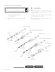
Linear Drive Specifications The linear actuators shall be designed for seating and reclining operations. It adjusts the column to the required level by raising and lowering it. The drive is provided by a DC motor with worm geat which acts on a trapexoidal threaded spindle drive or ball screw system. The actuators shall be protected against overheating by the Magnetic control unit. Amico actuators shall use a push / pull force. They shall have a self-locking function which is activated by a built-inbrake.
Linear Drive Dimensions 4.21” [107mm] 1.10” [28mm] 1.10” [28mm] 1.67” [42.5mm] 1.57” [40mm] 1.89” [48mm] +0.01” [ 0.3mm] O 0.47” [12mm] +0.004” [0.1mm] O 0.25” [6.3mm] 6.65” [169mm] +0.01” [ 0.3mm] O 0.47” [12mm] +0.004” [0.1mm] 2.6” [66mm] 2.6” [66mm] &RONT VIEW 3IDE VIEW RL = min. 7.68” [195mm] + stroke +_ 0.08” [2mm] 0.39” [10mm] 4.57” [116mm] 0.34” [8.7mm] " EARING INSERT FOR FORK HEAD 4OP VIEW Model Number Linear Drive = 30" [762mm] Column: C-X-ELEC-CYL-10 36" [914.
Servicing WARNING Always shut off source pressure at designated zone valves before servicing any gas outlet. The periodic inspection of gas outlets and electrical outlet is recommended to ensure proper safety and operation. A) Gas Outlet * Inspect the gas outlet connection points for the following: 1. Proper and legible identification. 2. Worn or defective engagement mechanisms. 3. Leaks. 4. Deformed or damaged threaded connections. 5. Loose fasteners.
www.amico.com Amico Architectural | www.amico.com 85 Fulton Way, Richmond Hill Ontario, L4B 2N4, Canada 71 East Industry Court, Deer Park NY 11729, U.S.A Toll Free Tel: 1.877.264.2697 Toll Free Fax: 1.866.440.4986 Tel: 905.763.7778 Fax: 905.763.8587 Email: info@amico.