
Operation Manual

12
INSTALLATION
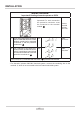
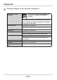
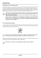
WIRING DIAGRAM
Important! Heating elements operate at 230V.
Recom-
mended
connec-
tion lead
1 For a 230 V single phase connection
with a neutral lead, terminals 1-2 are
bridged, neutral lead is connected
to terminal 4, and the protective
conductor to
1N~ OWY
3X 4 mm
2
2* For a 400/230 V two phase con-
nection with a neutral lead, termi-
nals 2-3 are bridged, neutral lead
is connected to terminal 4, and the
protective conductor to
2N~ OWY
4X2,5mm
2
L1=R, L2=S, L3=T, N=neutral lead connection, =protective lead terminal
* For domestic 3-phase 400/230V electrical system, connect the remaining wire to the
terminal: 3, which is not connected to the hob internal electrical system.
Important! For each connection
the protective conductor must
be connected to the terminal
marked