MODEL DECO 2000 DECORATIVE STITCHING MACHINE PARTS AND SERVICE MANUAL MACHINE SERIAL No.: PART NUMBER 97. 7000.0.002 This manual is valid from the machine serial No. N704652 (separated plate) N704655 (remiling) AMF is trademark of AMF Group, Inc.
MODEL DECO 2000 DECORATIVE STITCHING MACHINE PARTS AND SERVICE MANUAL MACHINE SERIAL No.: PART NUMBER 97. 7000.0.002 This manual is valid from the machine serial No. N704652 (separated plate) N704655 (remiling) AMF is trademark of AMF Group, Inc.
97.7000.0.002 97.7000.0.002 97.7000.0.002 97.7000.0.002 97.7000.0.002 97.7000.0.
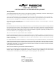
LIMITED WARRANTY ON NEW AMF REECE EQUIPMENT Warranty provisions: A ninety (90) day limited service labor warranty to correct defects in installation, workmanship, or material without charge for labor. This portion of the warranty applies to machines sold as ”installed” only. A one (1) year limited material warranty on major component parts to replace materials with defects. Any new part believed defective must be returned freight prepaid to AMF Reece, Inc. for inspection.
Warranty Registration Card (Please Fax or Mail immediately after installation) Note: All Warranty Claims Void, unless Registration Card on file at AMF Reece HQ Machine model number: (S101, S100, S104, S105, S211, Decostitch, S4000 BH,EBS Mark II, etc) Manufacturer‘s serial or production number: Installation Site Information: Customer‘s Name: Customer‘s Mailing Address: Customer‘s Telephone Number: Supervising Mechanic‘s or Technician‘s Name: Signature of Supervising Technician: AMF Reece Technician‘s Nam
DECO 2000 TABLE OF CONTENTS PAGE A - INTRODUCTION 1. Machine DECO 2000 Basic Functions and Advantages .......................................... 1-1 2. Basic Information .................................................................................................... 1-2 3. Specification ........................................................................................................... 1-3 4. Safety Labels and Device ..............................................................................
DECO 2000 TABLE OF CONTENTS PAGE E - STANDARD MACHINE ADJUSTMENT 1. Adjustment .............................................................................................................. 1-26 2. Adjustment of Needle Bars ...................................................................................... 1-29 3. Adjustment and Timing of the Gripper Fingers .......................................................... 1-31 4. Adjusting loop Support, Thread Guide and Separator Guide ......................
DECO 2000 A - INTRODUCTION 1 . M A C H I N E D E C O 2 0 0 0 B A S I C F U N C T I O N S A N D A D VA N TA G E S 1. Decorative machine Deco 2000 was created at AMF Reece company, so that the machine maximally imitate the hand stitching and allows to select and create the stitch style. The secret of this machine is principally at the special transitivity needle system.
DECO 2000 A - INTRODUCTION 2 . B A S I C I N F O R M AT I O N S The sewing machine Deco 2000 is designed and produced to be very reliable. Important design goals have been to provide a safe machine that is simple and inexpensive to maintain. Special electronic and mechanical safety devices protect the operator and the machine. There is a special power lock out switch that permits the machine to be locked in the off position, so that it cannot be cycled accidentally.
DECO 2000 A - INTRODUCTION 3 . S P E C I F I C AT I O N S Deco 2000 ATT Machine type Description Deco 2000 Pick Stitch Electronic decorative m achine Deco 2000 or s ewing ladies and m an jackets Stitch style 150 to 500 turns per m inute/ from 75 to 250 s titches per m inute Machine Performance Sew ing Speed 500 s .p.m .
DECO 2000 A - INTRODUCTION 4. S A F E T Y L A B E L S A N D D E V I C E * * * * — Deco 2000 ATT Ê Ë Ì Í Î 1-4 Warning Danger - possible injury Covers removed, possible injury Standard Label Needle Bar Cover Ï Ð Ñ Ò Ó Display Table Control Box Emergency Stop Button Hand Wheel Released 06/2010 E-mail: service@amfreece.cz; parts@amfreece.cz; website: www.amfreece.
DECO 2000 A - INTRODUCTION 5. G E N E R A L M A C H I N E PA R T S D E S C R I P T I O N Motor Sew Table Top Main Power Switch Start Button Foot Pedal Halogen Lamp Machine Head Reverse Button Knee Lever * Thread Trim * Large Tension Assembly * Thread Stand Released 06/2010 E-mail: service@amfreece.cz; parts@amfreece.cz; website: www.amfreece.
DECO 2000 A - INTRODUCTION 6. INSTRUCTIONS FOR THE SECURITY OF THE OPERATOR AND MAINTENANCE When the machine is set to the working area, it is recommended to keep the minimal distance said in the drawing. D A N G E R ! D o not place the machine close to the steam irons because higher temperature than is said in chapter Specifications can cause slight loss the quality of the waxed silk threads. Observe all directions said bellow.
DECO 2000 A - INTRODUCTION - In case when the operator will not work on the machine, disconnect the power supply by removing the plug from the socket. Do not adjust the machine in any way, which could endanger its safety. Every part of the machine can be dangerous, if there is incorrect manipulation or faulty maintenance with the machine. That is why everybody, who will manipulate, maintain or operate with this machine must be acquainted with informations included in this manual.
DECO 2000 A - INTRODUCTION 7. SPECIAL ACCESSORIES Size 36 needle for Medium weight with Fine Thread (part number 00103236) Size 38 needle for Medium weight with Medium Thread (part number 00103238) It is possible to use different needle sizes, but it is necessary to use different neeedle bar kit for specific needle. (see table) Part Number Extra Parts Description Nedle Bar Assembly Standard 70.4253.1.078* 70.4253.1.
DECO 2000 B - MACHINE ASSEMBLY 1. CONTENT OF THE SHIPPING BOX 1. The delivery usually contains one box, if it is not mentioned otherwise during the ordering. The box contain machine and dismount table. 2. In a box is also carton with accessories and operation instruction with spare parts manual. 3. When unpacking the delivery, follow labels which are on a cover. CAUTION: If the delivery was damaged during the transport, inform the carrier. Check the contains of the delivery with order.
DECO 2000 B - MACHINE ASSEMBLY 3. ACCESSORIES A package of accessories is supplied with this machine, please refer to page 3-52 for detailed descriptions. 4 . C O N N E C T I O N O F T H E M A C H I N E T O T H E P O W E R S U P P LY Power supply must be 208 to 230 volts 1 phase, 50 or 60 hertz. Receptacle plug must meet requirements of IEC standard 364-4-41, its circuit breaker must be minimal 10A with characteristic C according to the EN 60947-2 (or 16A with characteristic B).
DECO 2000 C MACHINE CONTROLS 1 . P OW E R U P 1.1.Connect the machine to the power supply of appropriate voltage 230 V. To start the machine turn the main switch Ę to position 1. 1.2.The display Í is activated and lit up. Information about AMF REECE and the program version recorded in the machine temporarily appears on the screen. R 1.3.This screen is automatically changed to the fault screen Î. This screen informs the operator of any machine faults.
DECO 2000 C MACHINE CONTROLS 2. C O N T R O L PA N E L D E S C R I P T I O N Main menu: 11 UP R READY SPEED 310 500 - + 150 STANDARD STITCH EDIT Ê Set sewing speed ( stitches per minute - s.p.m.). Ë Buttons for setting the sewing speed. Ì Press the Edit button to enter to the next menu to set the stitch length and stitch style. Í Set stitch style . Î Press the UP button to bring the machine to the home position -(the needle is up).
DECO 2000 C MACHINE CONTROLS 4. TO P S T I T C H A N D B OTTO M S T I T C H L E N G T H A D J U S T M E N T 1. To change the length of the Top stitch and Bottom stitch press the Edit button on the main screen. UP SPEED READY 310 500 - + 150 STANDARD STITCH EDIT 2. The screen for setting the parameters appears on the display. To change the size of the Top stitch, press the top stitch value on the screen Ê. t STYLE EDIT >> << STANDARD STITCH OK 3.
DECO 2000 C MACHINE CONTROLS CAUTION ! If the stitch length parameter is greater than the allowed range, this note appears on the screen: t 20 CRL R 6 7 8 9 SET NUMBER IS INCORRECT 2 3 4 5 STANDARD STITCH 0 1 ENT Press the arrow. The previous display appears on the screen. Set the required parameter within the maximum al lowed value of 63. NOTE ! If the stitch reverse facility is required, press the blue REVERSE button on the right side of the work table.
DECO 2000 C MACHINE CONTROLS 5 . S E T T I N G T H E S T I T C H S TY L E The standard stitch is created by repeating the Top and Bottom stitch lengths during sewing. As well as the standard stitch it is possible to select another four stitch styles and set ten different lengths of Top and Bottom stitches. The operator can create the stitch style and sequence of stitches as needed. 5.1.To change the stitch style, press Edit on the main screen. UP READY SPEED 310 500 - + 150 STANDARD STITCH EDIT 5.
DECO 2000 C MACHINE CONTROLS 5. The next numerical screen will appear on the display: 50 40 1 6 2 15 50 CRL 0 50 8 4 9 5 20 2 30 3 35 4 50 5 0 STYLE STITCH01 7 3 ENT OK 1 Set the required stitch length. The set stitch length is shown on the upper part of the screen Î. Press Enter to confirm the parameter. To keep the original set parameter press Clear. The buttons Enter and Clear always return you to the previous screen. Repeat the steps 4. and 5. until all required parameters have been set.
DECO 2000 C MACHINE CONTROLS 6. THREAD TRIM - LENGTH ADJUSTMENT 6.1 If you want to change the trimmed thread lenght, press EDIT button. UP READY SPEED 310 500 - + 150 STANDARD STITCH EDIT á 6.2 Press t button. t STYLE EDIT >> << STANDARD STITCH OK á 6.3 Press + or - for increasing or reducing the value. The shows the delay / start time of the cutting equiment after retacting the thread with the looper into the machine. EXIT 0.
DECO 2000 C MACHINE CONTROLS 7. CONDENSED STITCH 7.1 To select the condensed stitch parameters press EDIT button on the main screen. UP READY SPEED 310 500 - + 150 STANDARD STITCH EDIT 7.2 Press ‘DENSE’ on the new screen. This function is password protected if the “Condense Stitch Kit (Part no. 03.5570.0.013)” is ordered separately. To activate this function press the button and enter the password supplied along with the Dense Kit. t STYLE DENSE EDIT >> << STANDARD STITCH OK 7.
DECO 2000 C MACHINE CONTROLS 7.4 Then press ‘DENSE’ again and a new screen with dense stitch parameters would be displayed. t STYLE DENSE EDIT >> << STANDARD STITCH OK 7.5 Press ‘+’ or ‘-’ to select the desired total condense length or the length of stitch by pressing ‘+’ or ‘-’ buttons corresponding to parameter ‘Stitch Density’ Exit - + + 7.6 Condense stitch parameter may be selected anytime during stitching by pressing left foot pedal on the machine.
DECO 2000 C MACHINE CONTROLS 8. ADJUSTING THE MACHINE - PICK STITCH To the customer order it is possible to adjust the machine by a mechanical mechanism called the Bender to sew a Pick Stitch which simulates a hand stitch. To change the Standard style stitch to Pick Stitch see 1-44,45. After the machine is adjusted to sew a Pick Stitch , the Pick Stitch style Ê is shown on the screen.
DECO 2000 C MACHINE CONTROLS 9. S TA R T I N G S E W I N G Ensure that all set parameters concur with requirements. The machine is activated by one pedal (A), but it is possible to order the machine with two pedals (B). A B A - one pedal 1. If the machine is not in the home position with the needle up, press the foot pedal Ê in position 1 or the UP button on the left corner of the main screen 2. Move the knee lever Ë to the right. The foot will raise and you can place the material.
DECO 2000 C MACHINE CONTROLS 4. The information about the sewing speed and selected stitch style appears on the screen during the sewing. There is no possibility to change these parameters when the machine is running and run is displayed on the screen Î. RUN SPEED 150 310 500 + STANDARD STICH 10. E R RO R M E S S A G E S If the Error message appears on the screen a fault has occurred.
DECO 2000 C MACHINE CONTROLS 11. S W I T C H O F F T H E M A C H I N E Emergency stop: The machine can be stopped by the black STOP button at any time during sewing. Use this button in case of possible injury or machine damage. The button is located on the left side of the machine frame. The machine stops immediately when the Stop button is pressed. The error mes sages appears on the screen. OK CAUTION! Always remove the power supply to change the needle or make any other machine maintenance.
DECO 2000 D - CORRECT MACHINE APPLICATION 1 . N E E D L E I N S TA L L AT I O N Use only the needles number: 00103238 made in AMF Reece as is adduced in chapter Specifications page 3. This type of needles was developed in AMF Reece. Double pointed needle which has an eye at the mid point, allows to transmitting the needle from one needle bar to the other and during the sewing maximally imitate the shape of the hand sewing.
DECO 2000 D - CORRECT MACHINE APPLICATION 2. THREADING When threading see the pictures below. Easy threading allows the threading device located on the right side of the needle. 1. 2. Bring the needle to the home position by pressing the right foot pedal or by pressing the Up button on the display. Move the lever of threading device down, so that the hook passes through the needle eye. Place the thread behind a hook and release the thread device lever. Released 06/2010 E-mail: service@amfreece.
DECO 2000 E - STANDARD MACHINE ADJUSTMENT 1, ADJUSTMENT 1-26 Released 06/2010 E-mail: service@amfreece.cz; parts@amfreece.cz; website: www.amfreece.
DECO 2000 E - STANDARD MACHINE ADJUSTMENT * — SEQUENCE IN Released 06/2010 E-mail: service@amfreece.cz; parts@amfreece.cz; website: www.amfreece.
DECO 2000 E - STANDARD MACHINE ADJUSTMENT 1-28 Released 06/2010 E-mail: service@amfreece.cz; parts@amfreece.cz; website: www.amfreece.
DECO 2000 E - STANDARD MACHINE ADJUSTMENT 2. A D J U S T M E N T O F N E E D L E B A R S 1.) Adjust the upper needle bar 1.1. 1.2. 1.3. 1.4. Move the upper needle bar to its DWELL position. Use the square head adjustment on the rear of the rocker arm to move the needle bar up and down. First loosen the clamping screw. Use the gauge from the accessories 37771023 to measure 14,2 mm between the lip on the needle bar - not the sleeve to the throat plate. Adjust the upper needle bar to the gauge.
DECO 2000 E - STANDARD MACHINE ADJUSTMENT 1-30 Released 06/2010 E-mail: service@amfreece.cz; parts@amfreece.cz; website: www.amfreece.
DECO 2000 E - STANDARD MACHINE ADJUSTMENT 3. A D J U S T M E N T A N D T I M I N G O F G R I P P E R F I N G E R S 1) Align to the needle 1.1. 1.2. 1.3. Bring the gripper fingers into the closed position. Loosen two mounting screws holding the finger bracket Move the finger bracket to get 0,13 mm clearance between the needle and the end of the pads on the gripper fingers. Tighten the screws. 2) Adjust finger closing 2.1. 2.2. 2.3.
DECO 2000 E - STANDARD MACHINE ADJUSTMENT 1-32 Released 06/2010 E-mail: service@amfreece.cz; parts@amfreece.cz; website: www.amfreece.
DECO 2000 E - STANDARD MACHINE ADJUSTMENT 4. A D J U S T I N G L O O P S U P P O RT, T H R E A D G U I D E , A N D S E PA R AT O R G U I D E 1) Adjust the loop support 1.1. 1.2. 1.3. 1.4. Bring the gripper fingers into the closed position. Loosen clamping screw holding the loop support (pyramid). Move the loop support to align its edge with the top fingers on the gripper fingers. Bring the lower needle bar all the way up. Make sure that it clears the loop support. 2) Adjust the thread guide 2.1. 2.2. 2.
DECO 2000 E - STANDARD MACHINE ADJUSTMENT 1-34 Released 06/2010 E-mail: service@amfreece.cz; parts@amfreece.cz; website: www.amfreece.
DECO 2000 E - STANDARD MACHINE ADJUSTMENT 5. A D J U S T M E N T A N D T I M I N G O F T H E T H R E A D L I F T E R 1) Adjust lifter hook 1.1. 1.2. Move the thread lifter to complete its upward travel. Adjust the lifter hook to lift the thread fully into the slot of the separator guide. Do not pinch the thread. Tighten the screw. Check if the lifter hook is not touch by looper after adjustment. The lifter hook can not touch the looper! 6.
DECO 2000 E - STANDARD MACHINE ADJUSTMENT 1-36 Released 06/2010 E-mail: service@amfreece.cz; parts@amfreece.cz; website: www.amfreece.
DECO 2000 E - STANDARD MACHINE ADJUSTMENT 7. A D J U S T M E N T A N D T I M I N G O F T H R E A D T E N S I O N F I N G E R 1) Set forward position 1.1. 1.2. 1.3. Remove both throat plates. Bring the tension finger to its most forward position (forward operator). Loosen the support block pivot screw. Move the pivot to position the nose of finger at 4,8 to 6,4 mm from the center of the needle. Tighten the screw. 2) Timing the tension finger 2.1. 2.2. 2.3.
DECO 2000 E - STANDARD MACHINE ADJUSTMENT 1-38 Released 06/2010 E-mail: service@amfreece.cz; parts@amfreece.cz; website: www.amfreece.
DECO 2000 E - STANDARD MACHINE ADJUSTMENT 8. A D J U S T M E N T A N D T I M I N G O F M AT E R I A L F E E D 1) Position the timing of material feed 1.1. 1.2. 1.3. Bring the eye of the needle flush with the throat plate. Loosen the throat plate holder, by two screws, holding the throat plates. Position the throat plate for 0,08 a• 0,13 mm clearance of the forward end of the slot from needle eye. Make sure that the feed dog and the bender plate are free to operate.
DECO 2000 E - STANDARD MACHINE ADJUSTMENT 1-40 Released 06/2010 E-mail: service@amfreece.cz; parts@amfreece.cz; website: www.amfreece.
DECO 2000 E - STANDARD MACHINE ADJUSTMENT 9. T I M I N G T H E F O L L O W E R F O O T 1) Adjust the follower foot separation 1.1. This adjustment requires a long arm key or an extension to a standard key. Bend the key as required for access to the gear screw. 1.2. Remove the belt guard. Unhook the cam lever spring for the upper looper. 1.3. Rotate the handwheel to bring the set on the presser foot gear into view. Loosen the set screw. 1.4.
DECO 2000 E - STANDARD MACHINE ADJUSTMENT 1-42 Released 06/2010 E-mail: service@amfreece.cz; parts@amfreece.cz; website: www.amfreece.
DECO 2000 E - STANDARD MACHINE ADJUSTMENT 10. A D J U S T M E N T A N D T I M I N G , L E F T L O O P E R A N D R I G H T L O O P E R 1) Left looper dwell position 1.1. Loosen two screws to remove the belt guard at the handwheel and of the machine for access to the cam lever. 1.2. Bring the upper needle bar to its maximum upward position. 1.3. Loosen the cam lever screw and locate the tip of the left looper at 4,8 mm from the needle. 2) Left looper clearance 2.1. 2.2.
DECO 2000 E - STANDARD MACHINE ADJUSTMENT 1-44 Released 06/2010 E-mail: service@amfreece.cz; parts@amfreece.cz; website: www.amfreece.
DECO 2000 E - STANDARD MACHINE ADJUSTMENT 1 1. A D J U S T M E N T A N D T I M I N G O F L O W E R L O O P E R 1) Timing the drive gibs 1.1. Rotate the handwheel by hand to transfer the needle to the upper needle bar. Stop at the point that the retainer ring on the upper needle bar (moving upward) is just flush with the bottom of the needle bar bushing. 1.2. Loosen the arm crank screw. Hold the arm crank assembly and move the lower looper arm out far enough to remove the arm crank. 1.3.
DECO 2000 E - STANDARD MACHINE ADJUSTMENT 1-46 Released 06/2010 E-mail: service@amfreece.cz; parts@amfreece.cz; website: www.amfreece.
DECO 2000 E - STANDARD MACHINE ADJUSTMENT 1 2. A D J U S T M E N T A N D T I M I N G O F B E N D E R P L AT E 1) Raised position of bender plate 1.1. 1.2. 1.3. 1.4. Loosen two screws to remove the metal table - holder of the throat plates. Release the angle plate latch for pick stitch operation. Rotate the handwheel to bring the bender plate fully up. Loosen the screw attaching the pusher plate. Lift the presser foot away from the bender plate. Move the bender plate for 0,4 mm clearance from the needle.
DECO 2000 E - STANDARD MACHINE ADJUSTMENT 1-48 Released 06/2010 E-mail: service@amfreece.cz; parts@amfreece.cz; website: www.amfreece.
DECO 2000 E - STANDARD MACHINE ADJUSTMENT 5) Adjust the angle plate latch 5.1. 5.2. 5.3. Rotate the handwheel to bring the roller onto the high section of the angle plate cam on the main cam shaft. Loosen the mounting of the angle plate latch two screws on the tie bracket. Adjust the latch to snap onto locking clip. Tighten the mounting. 6) Adjust cam lever spring 6.1. 6.2. 6.3. Loosen the jam nut on the stud attaching the cam lever spring to tie bracket.
DECO 2000 E - STANDARD MACHINE ADJUSTMENT 1 3. S T E P M O T O R S E T U P Set up the gap 0,25 mm between the sensor face and flag on the cam. 1-50 Released 06/2010 E-mail: service@amfreece.cz; parts@amfreece.cz; website: www.amfreece.
DECO 2000 E - STANDARD MACHINE ADJUSTMENT 1 4. S E T T I N G - U P P R O C E D U R E F O R F E E D D O G S E N S O R A N D F L A G Ensure 0,8 mm gap between feed dog sensor and assembly. Sensor cable harness connector must be fitted into SK 3 on main card. Check correct mains voltage setting is selected. Switch on machine. Pull the handwheel round by hand keeping an eye on feed dog as feed dog goes below throat plate - stop. Adjust flag assembly next to feed dog sensor so small red L.E.D. just comes on.
DECO 2000 E - STANDARD MACHINE ADJUSTMENT 1 5. B E LT T E N S I O N A D J U S T M E N T S The V belt can be released after some time of using the machine, which may worsen the productivity. That is why its necessary to check the belt tension. 1. 2. 3. 4. 5. 1-52 To tighten the V belt fold the machine working table and loosen two nuts 06000014 and two screws 0400004. Move the bracket down as needed and tighten two nuts.
DECO 2000 F - MACHINE MAINTENANCE 1. PRINCIPLES OF MACHINE MAINTENANCE W A R N I N G : - To make any maintenance turn off the main switch. - Do not modify the machine in any way, which could damage electronic devices and machine mechanisms. C A U T I O N : - Always keep the safety rules valid in the organization. WA R N I N G : -Check if the electrical cables are not damaged. -Check safety covers for damage and replace if needed immediately.
DECO 2000 F - MACHINE MAINTENANCE 2. M A C H I N E C L E A N I N G A N D M A I N T E N A N C E 1. Switch off the electrical power supply. 2. Use the brushes from the accessories to clean the thread lints and fabric from the sewing mecha nism. Turn the handwheel to rotate with the sewing mechanism. Clean the thread waste from the roller daily. Lift the working table and perform the cleaning by the air-blowing. Do not forget to clean the waste on the control box air gird.
DECO 2000 F - MACHINE MAINTENANCE Released 06/2010 E-mail: service@amfreece.cz; parts@amfreece.cz; website: www.amfreece.
DECO 2000 F - MACHINE MAINTENANCE 4. P E R I O D I C M A I N T E N A N C E once a day (10 hours of operation) -cleaning of the sewing mechanism area -cleaning the inner frame of the machine -lubrication of the needle bars and sewing mechanisms once a week (80 hours of operation) once a month (300 hours of operation) -visual check - external and internal mechanism -check the screw connections tightening -check the waste on the control box air grid. -check the belts tension 5. MACHINE DISPOSAL 1.
DECO 2000 TROUBLESHOOTING TABLE OF CONTENTS Page Introduction .......................................................................................................... 2-2 Adjustments quick reference list ............................................................................ 2-2 FAULTS WITHOUT ERROR MESSAGES Thread breakage................................................................................................... 2-3 The machine does not sew .................................................
DECO 2000 TROUBLESHOOTING 1. INTRODUCTION Warning! Inspect the machine on a regular basis and use only quality parts. The manufacturer recommends using original AMF Reece parts, especially needles, loopers, and throat plates. The Deco 2000 electronically displays error massages, when worn or damaged parts are detected. If machine problems occur and the error is not displayed, ensure correct needle installation and threading. The other troubles are eliminated according to the detailed descriptions listed.
DECO 2000 TROUBLESHOOTING 3. F A U LT S W I T H O U T E R R O R M E S S A G E S SYMPTOM Thread breakage. POSSIBLE CAUSE Thread draw - off is too tight. PROBABLE SOLUTION Reduce thread tension Damaged loopers or throad plate. Replace damaged parts. Incorrect needle and sewing mechanism adjustment. Poor thread quality. Thread holes in the needle and looper are too small. The machine does not sew. Skip stitches. The needle transfer does not work, needle breakage.
DECO 2000 TROUBLESHOOTING 4. T H E E L E C T R O N I C S Y S T E M E R R O R M E S S A G E S If the Error message Ê appears on the screen a fault has occurred. Press button Ê. UP ERROR SPEED 310 500 - + 150 STANDARD STITCH EDIT Next a list of errors appears on the screen. This message informs the operator what is wrong. Repair the machine. Press button Ë. For more informations see table bellow.
DECO 2000 TROUBLESHOOTING 5 . E L E CTRONIC SYSTEM FAULTS - fuse description FUSE TYPE INSURED PART FAULT Work light The light does not operate The source GS 1 primary part. The LED on GS 1 is not light. The LED on PLC is not light. The display is not light. F 2 - T10A 12.0008.4.664 Frequency inventer U 1. Frequency inventer faults. F 3 - T1,6A 12.0008.4.064 The source GS 2 primary part. The source GS 2 secondary part. Step motor faults. F 1 - T2A, 12.0008.4.665 . F 4 - T 10A 120008.4.664.
DECO 2000 TROUBLESHOOTING 6. T H E E L E C T R O N I C FA U LT S SYMPTOM After the machine is switched on, the display is not light. POSSIBLE CAUSE No power supply. Power switch QS 1 is damaged. PROBABLE SOLUTION Check main power supply or voltage in the socket. Replace the switch 12.0008.4.835. Fuse F 1 failure (the LED on the source does not light). Replace the fuse 12.0008.4.665. Faulty display. Replace the display 70.8001.1.003. Contactor KM 1 does not switch on.