CATRAC & SnapTrac Cable & Hose Carrier Products ® ® CATRAC Cable & Hose Carrier Products Ordering Guide & Technical Information Ordering Guide & Technical Information
CATRAC® is used on various types of machinery as a means of safely and efficiently conveying power, electrical, air, or fluid (or a combination of these) to equipment in motion. CATRAC is designed to be maintenance free and to protect cables and hoses from abrasion, wear and twisting. A wide variety of options are available.
CATRAC® CATRAC SelectionGuide Guide Selection If you need assistance or have any questions on special applications, feel free to contact our application engineers. Max. Unsupported Length in Feet 1. Determine the outside diameter of the largest cable or hose to be carried. 2. Determine total machine travel. Unsupported length of CATRAC® on horizontal applications is total travel ÷ 2 when no supports are used and the stationary mounting foot is placed at the center line of travel. 3.
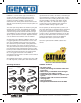
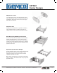
CATRAC® CATRAC CarrierDesigns Designs Carrier RC Rod Carriers Available on 2CP, 3CP, 203, 375, 304 style tracks, this tubing is used to hold the entire CATRAC® together. They are fastened to links with a self tapping screw that can be removed from top or bottom rod to make installation of hose or cable easier. WC Welded Carriers The carrier is widely used in very rugged applications. It can withstand severe hydraulic shock and has no loose parts which can be lost during installation of the hose cable.
CATRAC CATRAC ® Carrier Designs Carrier Designs AB Split Bar Carriers 1/2” wide aluminum or 3/4” wide wood split bar carriers can be provided. This carrier is custom machined to your specifications. Note: Holes must be at least 1/8” larger than cable hose diameter. VP Vertical Pins Vertical pins, also referred to as separators or dividers, can be welded into RP, SL and WC style carriers to separate cables or hoses to prevent twisting or overlap.
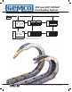
® 2CP and 3CP CATRAC 2CP and 3CP CATRAC® Part Number Part NumberSystem System 8060 2CP 2.75 04 CATRAC CATRAC Side Link 2CP 2CP Overall Height “M” 7.50 11.50 13.25 2CP *Consult factory for special radius. Ass’y Weight/Ft. 3# 3CP 3CP Radius “R”* 2.75 4.75 5.63 5.13 6.63 8.19 10.90 15.13 13.25 16.25 19.38 24.80 33.25 Carrier Width* 02 04 06 08 *Consult factory for special widths. 3CP 04 06 08 10 12 Ass’y Weight/Ft. 5# Weight based on 8” carrier.
® ® 2CP and and 3CP 3CPCATRAC CATRAC 2CP Part Number NumberSystem System Part WC P Style WC 2CP 1.25 3CP 2.00 Style SL RC P Pin & Retaining Ring Construction NOTE: CATRAC Length must be divisible by pin centers for that style. Spring Loaded Removable Pipe HC 2CP 1.20 3CP 1.90 Style Rod Carrier HC 2CP 1.18 3CP 1.90 Style AB Welded Carrier HC Length Split Aluminum Bar Carrier Max. DIA. 2CP 1.25 3CP 2.00 Standard Mounting Feet CATRAC Style Horiz. Mount Feet P/N Vert.
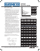
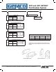
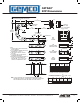
CATRAC®® CATRAC 2CP Dimensions Dimensions 2CP 2.00 CLEARANCE REQUIRED ABOVE LINKS Z T TOTAL TRAVEL 1.50 1.50 HORIZONTAL MTG. FEET M OVERALL HEIGHT RADIUS 3.00 VERTICAL MTG. FEET .75 T/2 HALF TRAVEL .41 X .75 MOUNTING SLOTS TYPICAL T/2 HALF TRAVEL C A CENTER LINE OF TRAVEL Y** Y** B X (SEE BELOW) (RC) ROD CARRIER 2.00 3.00 E .50 1.50 1.18 .41 (SL) SPRING LOADED REMOVABLE PIPE NOTE: 1) CATRAC LENGTH MUST BE DIVISIBLE BY PIN CENTERS.
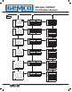
® CATRAC CATRAC® 3CP Dimensions Dimensions 3.00 CLEARANCE REQUIRED ABOVE LINKS Z T TOTAL TRAVEL 1.75 3.00 HORIZONTAL MTG. FEET M OVERALL HEIGHT RADIUS 6.00 VERTICAL MTG. FEET 1.50 T/2 HALF TRAVEL .41 X .75 MOUNTING SLOTS TYPICAL T/2 HALF TRAVEL C A CENTER LINE OF TRAVEL Y** Y** B X (SEE BELOW) E (RC) ROD CARRIER 3.00 5.75 1.00 3.00 1.90 .55 (SL) SPRING LOADED REMOVABLE PIPE NOTE: 1) CATRAC LENGTH MUST BE DIVISIBLE BY PIN CENTERS.
® ® Mill-Duty CATRAC Mill-Duty CATRAC Part NumberSystem System Part Number 8060 203 2.75 4 CATRAC CATRAC Side Link 203 203 2.75 4.75 5.63 8.69 Overall Height “M” 7.50 11.50 13.25 19.38 5.13 6.63 8.19 10.90 15.13 13.25 16.25 19.38 24.80 33.25 5.62 7.37 11.12 14.87 24.12 15.00 18.50 26.00 33.50 52.00 5.88 7.44 10.15 14.38 21.25 16.25 19.38 24.80 33.25 47.00 11.00 14.81 20.50 24.12 28.00 35.62 47.00 54.25 10.50 12.50 19.50 23.12 29.00 33.00 47.00 54.
® ® Mill-Duty CATRAC Mill-Duty CATRAC Part NumberSystem System Part Number WC WC VP Style 203 304 375 456 606 808 Welded Carrier HC 1.25 2.00 2.75 3.50 4.50 6.50 BC Welded Vertical Pins On Carrier Types RP, SL & WC No Charge SL RP AB Style 203 304 375 456 606 808 Style 203 304 375 456 606 808 Removable Pipe HC 1.10 1.93 2.67 3.14 4.37 6.00 Split Aluminum Bar Carrier Max. Hole 1.25 2.00 2.75 3.50 4.50 6.50 X BC Snap Ring Const. Bolted Const.
CATRAC CATRAC®® 203 Dimensions Dimensions 2.00 CLEARANCE REQUIRED ABOVE LINKS Z T TOTAL TRAVEL 1.50 1.50 HORIZONTAL MTG. FEET M OVERALL HEIGHT RADIUS 3.00 VERTICAL MTG. FEET .75 T/2 HALF TRAVEL .38 X .56 MOUNTING SLOTS TYPICAL T/2 HALF TRAVEL C A CENTER LINE OF TRAVEL Y** Y** B X (SEE BELOW) 2.00 3.50 .50 1.50 E (RP) REMOVABLE PIPE 1.10 .38 (SL) SPRING LOADED REMOVABLE PIPE NOTE: 1) CATRAC LENGTH MUST BE DIVISIBLE BY PIN CENTERS.
CATRAC® 304 Dimensions 3.00 CLEARANCE REQUIRED ABOVE LINKS Z T TOTAL TRAVEL 1.75 1.00 1.00 1.00 1.50 HORIZONTAL MTG. FEET M OVERALL HEIGHT RADIUS T/2 HALF TRAVEL 6.00 VERTICAL MTG. FEET .41 X .75 MOUNTING SLOTS TYPICAL T/2 HALF TRAVEL C A CENTER LINE OF TRAVEL Y** Y** B X (SEE BELOW) 3.00 5.75 1.00 3.00 E (RP) REMOVABLE PIPE 1.93 .50 (SL) SPRING LOADED REMOVABLE PIPE NOTE: 1) CATRAC LENGTH MUST BE DIVISIBLE BY PIN CENTERS. 2) ALL STANDARD CARRIER WIDTHS IN 2" INCREMENTS 4" THRU 18".
CATRAC CATRAC®® 375 Dimensions Dimensions 3.75 CLEARANCE REQUIRED ABOVE LINKS Z T TOTAL TRAVEL 2.13 .41 X 1.27 MOUNTING SLOTS M OVERALL HEIGHT RADIUS 6.00 3.00 HORIZONTAL MTG. FEET VERTICAL MTG. FEET 1.50 T/2 HALF TRAVEL .41 X .75 MOUNTING SLOTS T/2 HALF TRAVEL C A CENTER LINE OF TRAVEL Y** Y** B X (SEE BELOW) (RC) ROD CARRIER 3.75 6.13 E .75 3.00 2.67 .54 (SL) SPRING LOADED REMOVABLE PIPE NOTE: 1) CATRAC LENGTH MUST BE DIVISIBLE BY PIN CENTERS.
CATRAC CATRAC®® 456 Dimensions Dimensions 4.50 CLEARANCE REQUIRED ABOVE LINKS Z T TOTAL TRAVEL 3.50 1.00 1.00 1.00 1.50 HORIZONTAL MTG. FEET M OVERALL HEIGHT RADIUS T/2 HALF TRAVEL 6.00 VERTICAL MTG. FEET .41 X .75 MOUNTING SLOTS TYPICAL T/2 HALF TRAVEL C A CENTER LINE OF TRAVEL Y** Y** B X (SEE BELOW) 4.50 6.00 .75 3.00 E (RP) REMOVABLE PIPE 3.14 .50 (SL) SPRING LOADED REMOVABLE PIPE NOTE: 1) CATRAC LENGTH MUST BE DIVISIBLE BY PIN CENTERS.
CATRAC® 606 Dimensions 16 6380 Brockway Road • Peck, MI 48017 • 800.325.8074 • 810.378.5511 • Fax 810.378.5516 • www.AMETEKAPT.
CATRAC® 808 Dimensions 6380 Brockway Road • Peck, MI 48017 • 800.325.8074 • 810.378.5511 • Fax 810.378.5516 • www.AMETEKAPT.
StationaryRoller Roller Stationary Part Number NumberSystem System Part PD-486 Stationary Roller Support 203 5.63 4 CATRAC Style 203 Radius 5.63 8.69 B Dim. 11.25 17.38 304 5.13 6.63 8.19 10.90 15.13 10.25 13.25 16.38 21.80 30.25 375 5.62 7.37 11.12 14.87 24.12 11.25 14.75 22.25 29.75 48.25 5.88 7.44 10.15 14.38 21.25 11.75 14.88 20.30 28.75 42.50 11.00 14.81 20.50 24.12 22.00 29.62 41.00 48.25 10.50 12.50 19.50 23.12 21.00 25.00 39.00 46.
RetractableRoller Roller Retractable Part Number NumberSystem System Part PD-1218 304 CATRAC Style 304 Retractable Roller Support 8 Radius 5.13 6.63 8.19 10.90 15.13 B Dim. 11.13 14.13 17.26 22.68 31.13 5.62 7.37 11.12 14.87 24.12 12.13 15.63 23.13 30.63 49.13 456 5.88 7.44 10.15 14.38 21.25 12.63 15.76 21.18 29.63 43.38 606 11.00 14.81 20.50 24.12 22.88 30.50 41.88 49.13 375 808 Carrier Width 8.00 x Nuts Out 5.13 10.50 12.50 19.50 23.
CATRAC®®Carriage Carriage CATRAC SupportSystem System Support Carriage Support Systems Carriage support systems are used when cable/hose loads and travel exceed the limits available with fixed roller supports and designed for applications requiring long travels, high speeds, quick accelerations and constant cycling. These systems are normally used in Section AA 20 20 Section BB conjunction with 304 and 456 CATRAC styles. Special Mill-Duty carriage support systems are available for extreme environments.
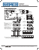
CATRAC Applications CATRAC®®Applications CATRAC® Applications Primary Metals Tundish Cars Ladle Cars Torch Cut Off Machines Slab Markers Mud Gun Ladle Lance Pickling Line Strip Mills Furnaces “Dummy” Bar Continuous Annealing Lines Packaging/Material Handling Palletizers Wrappers Shuttles Rubber Tired Vehicles Factory Automation Automation Storage & Retrieval System Construction Machinery Manlifts Aerial Lifts Utility Trucks Underground Boring CATRAC Automotive Applications Milling/Drilling Machinery Dri
Steel Mill MillApplications Applications Steel Mining - Iron Ore - Coal Limestone Ore Beneficiation Preparation Cleaning Belt Trippers Stackers Reclaimers Bedding Machines Trenchers Shipping - Rail - Water - Raw Material Storage Stackers Reclaimers Belt Trippers Car Dumpers Integrated Steel Making Plants Raw Material - Storage & Preparation Stackers Reclaimers Belt Trippers Car Dumpers Trenchers Sinter Plants Belt Trippers Bedding Machine Trenching Machine Reclaimer Coke Oven Batteries Coal Preparation - Co
Steel SteelMill MillApplications Applications Hot Strip Mills Primary Rolling Roll Sleds, Backup and Work Roll Vertical Scale Breaker Horizontal Scale Breaker Roughing Mills Finishing Mills Descale Systems Morgoil Lubrications Coilers Mandrel Carriage Stripper Cars X-Ray Machines Finishing - Processing Transfer Cars Oil Buggies Combo Line Skin Pass Line Slitters & Shears Coil Carrier Hook Walking Beam Coil Transfer Auxiliaries Transfer Cars Work Rolls Backup Rolls Bearing Extractor Car Sheet Mills - Cold
® Mill-Duty CATRAC Mill-Duty CATRAC® CATRAC® MD for the Primary Metals Industry Available in Any and ALL Sizes This industry readily accepts only those products that are made exceptionally strong to the point of being “overbuilt”. If the product doesn’t look like it belongs in that environment, it doesn’t. Made to any width or radius with more hose and cable carrying capacity in a box beam carrier, it can handle 8” I.D. hose or 12” O.D. cable.
CATRAC Options CATRAC®®Options Chip Covers Stainless steel chip covers protect hoses against damage from hot metal chips. The chip covers fit over the full length of the CATRAC® assembly, on either the top or bottom or both sides for maximum protection. The ends of the chip covers extend six inches beyond the ends of the CATRAC assembly for attachment. Chip covers should be fastened on either end to allow them to roll with the CATRAC. When ordering, specify either outside or inside covers or both.
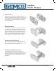
SnapTrac SnapTrac® ® Nylon Carriers Nylon Carriers Available in a Variety of Sizes Technical Characteristics SnapTrac® was developed to offer a light weight, low cost carrier for protected and controlled movement of cables and hoses. This corrosion resistant, nonconductive carrier is made of a longwearing nylon composition. SnapTrac can be used with electric, air, gas or hydraulic hoses. Light and secure even at high speeds, SnapTrac carriers will provide protection for the components inside the carrier.
® SnapTrac SnapTrac® Nylon Carriers Nylon Carriers Light SnapTrac Light series SnapTrac with small to medium sections for applications where high filling weight is not required. Light SnapTrac Series A External Width mm 8061SR200 8061SR250 B External Height mm C Inner Width mm D Inner Height mm R Bending Radius mm 18-41 15 12-35 12 18-40 23 22 15 18 40 8061SR30090 29-49 23.5 18-38 18.5 33-100 8061SR325A 57-120 37 40-103 25.5 50-150 8061SR325 55-118 37 40-103 25.
® ® SnapTrac SnapTrac NylonCarriers Carriers Nylon Medium SnapTrac Small to medium size SnapTrac with yellow connecting pivot pins offer high capacity in high performace applications. Available with snap open cover or closed styles.
® ® SnapTrac SnapTrac NylonCarriers Carriers Nylon Heavy SnapTrac A strong design with triple connecting pivot pins. This design allows unsupported length up to 6.5 m and extends the service life of the SnapTrac and cables. Heavy SnapTrac Series A External Width mm B External Height mm C Inner Width mm D Inner Height mm R Bending Radius mm 8061SR308SI/SE 82-394 75 38-350 57 150-400 8061SR309SI/SE 120-420 100 64-364 75.
® ® SnapTrac SnapTrac NylonCarriers Carriers Nylon Sliding SnapTrac Sliding SnapTrac is made to be used where travel distance is long. The links are equipped with skids, allowing the trac to slide on itself. It is made of special polymers to reduce friction and wear.
® CATRAC CATRAC® Development Sheet Development Sheet Please fill in completely and accurately and fax to the CATRAC Sales Department @ (810) 378-5516. Customer Information Contact Name Fax Company Email Phone Date Machine / Environment Specifications Machine Type or Name Machine Total Travel Distance Direction / Orientation of Travel ❑ Horizontal ❑ Vertical ❑ Side Running ❑ Other If other, please provide sketch.
Other Products Copyright 2010 by AMETEK AUTOMATION & PROCESS TECHNOLOGIES. All Rights Reserved. Made in the USA. 1080 N. Crooks Road, Clawson, MI 48017-1097 Phone: 248.435.0700 Toll Free: 800.635.0289 Fax: 248.435.8120 www.ametekapt.com 8060.C5R 3/10.