Series Series953 956 INSTALLATION MANUAL LINEAR DISPLACEMENT TRANSDUCERS 953A ™ VMAX Linear Displacement Transducer ABSOLUTE PROCESS CONTROL KNOW WHERE YOU ARE...
Contents Chapter 1: 953A Overview Chapter 1: 953A Overview.....................................2 Chapter 2: Installing...............................................4 2.1 Installing to a Mounting Bracket.........................4 2.2 Installing in a Hydraulic Cylinder........................5 Chapter 3: Wiring ...................................................8 3.1 V0/V1 (Voltage)..................................................8 3.2 C4/C2 (Current)..................................................8 3.
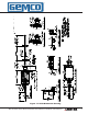
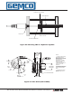
Figure 1-1 953A Dimension Drawing ® 1080 N. Crooks Road • Clawson, MI 48017 • 800.635.0289 • Phone 248.435.0700 • Fax 248.435.8120 • www.ametekapt.
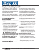
Chapter 2: Installing the LDT If a mounting bracket or other part is used that is made of ferromagnetic material (a material readily magnetized), it should be placed no closer than 0.25" from the LDT's rod end to minimize the effects of magnetic flux distortion. This can cause an inaccurate measurement of the magnet position.
.28 2 PLACES 2.00 1.25 .28 X 1.03 SLOT .37 1.00 C L .44 DEAD BAND STROKE NULL PROBE MOUNTING KIT (P/N 949003) 1.00 1.03 OPTIONAL MAGNET 2.00 PROBE 1.75 HEX 2.00 3/4-16 JAM NUT SUPPLIED W/PROBE OR OPTIONAL S .62 1.00 NOTES: UNLESS OTHERWISE SPECIFIED 1. MOUNTING KITS FURNISHED WITH MOUNTING BOLTS. 2. MOUNTING BRACKETS ARE MADE FROM 3/16" X 2" X3" STAINLESS STEEL. 2.00 1.25 .38 1.407 MAGNET MOUNTING KIT (P/N 949005) .75 THRU S .187 THRU (2 PLACES) .28 2 PLACES N N .406 N S S 2.
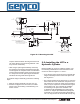
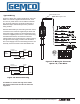
• An O-ring is provided at the base of the LDT’s mounting hex for pressure sealing. The O-ring seal was designed to meet Mil-Std-MS33656. Refer to SAE J514 or SAE J1926/1 for machining of mating surfaces. • A chamfered rod bushing in front of the magnet may be required. It is recommended that a chamfered rod bushing be used with LDTs having a rod 60.0” or longer. This bushing will prevent wear on the magnet assembly (wear occurs as the piston retracts from extended lengths).
STANDARD 4-HOLE MAGNET 0.5” BORE MINIMUM O-RING SEAL MAGNET SPACER OPTIONAL ROD BUSHING Figure 2-2: Mounting LDT in a Hydraulic Cylinder 1.18 RECOMMENDED MIN. SPOTFACE DIAMETER SEE NOTE 1 A .004 .866 .813 +/-.002 MINIMUM SEE NOTE 2 NOTES: .008 125 .094 MAX. .106 +/-.008 R.015 MAX. R 1. IF FACE OF PORT IS ON A MACHINED SURFACE, DIMENSIONS 1.180 AND .094 NEED NOT APPLY AS LONG AS R.008/.0004 IS MAINTAINED TO AVOID DAMAGE TO THE O-RING DURING ASSEMBLY. A 1.100 SEE NOTE 4 45° .008 .004 1.
Chapter 3: Wiring Once the LDT has been installed, wiring connections can be made. The VMAX has four different connector options. Please refer to the part number label to help identify which wiring diagram is correct. There are two groups of connections that will need to be made. They are as follows: • Power Supply Connections (including grounding and shielding) • LDT Input/Output Connections Power Supply/Ground Connections The 953A VMAX is available with many different connector/wiring options.
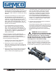
Cable # 949011LXX NOTE: XX= Length in feet Typical Wiring + Power Supply 7-30 VDC _ Position Output Customer Supplied Power Power Supply Common 953A LDT Position Common + Input TM With the Differential Input, the Analog Common wire is connected to the customer supplied input device and the Power Supply Common is wired separately to the customers supplied power source.
AUTOMATION & PROCESS TECHNOLOGIES TM Figure 3-4: Wiring for Connector Option "C", Integral Cable Assembly 10 Figure 3-5: Wiring for Connector Option "H", High Temp Integral Assembly ® AUTOMATION & PROCESS TECHNOLOGIES 1080 N. Crooks Road • Clawson, MI 48017 • 800.635.0289 • Phone 248.435.0700 • Fax 248.435.8120 • www.ametekapt.
Cable # SD0553300LXX NOTE: XX= Length in feet Cable # SD0553400LXX NOTE: XX= Length in feet AUTOMATION & PROCESS TECHNOLOGIES AUTOMATION & PROCESS TECHNOLOGIES TM TM Figure 3-7: Wiring for Connector Option "B", 8 Pin DIN, Voltage Output Figure 3-6: Wiring for Connector Option "B", 8 Pin DIN, Current Output ! CAUTION: Pinout is different for voltage vs. current models with connector option "B" ® 1080 N. Crooks Road • Clawson, MI 48017 • 800.635.0289 • Phone 248.435.0700 • Fax 248.435.8120 • www.
Cable # SD0553200LXX NOTE: XX= Length in feet Cable # SD0439700LXX NOTE: XX= Length in feet AUTOMATION & PROCESS TECHNOLOGIES AUTOMATION & PROCESS TECHNOLOGIES TM TM Figure 3-8: Wiring for Connector Option "E", 10 Pin MS Connector 12 Figure 3-9: Wiring for Connector Option "M", 6 Pin DIN ® AUTOMATION & PROCESS TECHNOLOGIES 1080 N. Crooks Road • Clawson, MI 48017 • 800.635.0289 • Phone 248.435.0700 • Fax 248.435.8120 • www.ametekapt.
3.3: Features Automatic Gain Control The Automatic Gain Control feature will automatically search and find the magnet on power up, if power is applied without a magnet on the LDT, the LED will turn RED indicating no magnet signal is detected. Turn power off and place magnet within the active stroke area. Re-apply power. Diagnostic LED LED Color Description None No power to LDT Green Magnet signal detected and within programmed range. Yellow Magnet signal detected, but magnet is outside of programmed range.
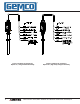
Optional Remote Tester & Programmer Optional In-Line Programmer The battery operated remote tester / programmer is available in either a voltage or current model. P/N SD0528810 is designed for voltage units while SD0528811 is for current units. Both units are designed to work with connector option S only. These units are typically used to demonstrate the functionality of the LDT in the field, however, they can be used as a handy troubleshooting / programming device.
Appendix B: Part Numbering to power the LDT. When powering more than one VMAX on a single power supply, remember that each unit requires approximately one watt of power. The amount of current draw will vary based on the input voltage used. To calculate the current draw for a particular LDT, divide the LDT wattage by the input voltage. For example, 1 watt divided by 24 VDC equals 41.6mA.
Appendix C: Specifications Rod End Mounting Hex Mounting Threads Head Assembly Head Enclosure Connector Displacement Dead Band Null Zone Linearity Repeatability Hysteresis Operating Temperature Head (Electronics) Guide Tube Storage Temperature Operating Pressure Guide Tube Pressure Shock & Vibration Shock Vibration Zero & Span Adjustability Approvals Input Voltage Current Draw General Specifications 316 Stainless Steel, 0.405" (10.29 mm) outer diameter 316 Stainless Steel, 1.75" (44.
NOTES: Part Number Serial Number Purchase Order Number Sales Order Number Comments
Other Products ® Copyright 2012 by AMETEK Automation & Process Technologies. All Rights Reserved. Made in the USA. ® AUTOMATION & PROCESS TECHNOLOGIES 1080 N. Crooks Road, Clawson, MI 48017-1097 Phone: 248.435.0700 Toll Free: 800.635.0289 Fax: 248.435.8120 www.ametekapt.com 953A.M3R 4/12.