
Owner's manual


6
0
1
2
3
4
5
6
7
8
9
0
1
2
3
4
5
6
7
8
9
0
1
2
3
4
5
6
7
8
9
0
1
2
3
4
5
6
7
8
9
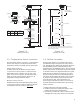
DM231
Status LED
Power /
4-20 mA Converter
Status LED
MODBUS RTU/ASCIIPower 9-30 VDC
Wiring Colors
Power
+VDC
-VDC
Ground
USA
Red
Black
Green
EU
Brown
Black
White
JP1
Terminating Resistor
Installed
Not Installed
}
}
1
2
3
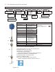
Figure 1.4 - 7231 Wiring
(Switches and jumpers shown in the default positions.)
1.7 - 7231 Modbus Set Up
The 7231 uses the Modbus protocol for communicating
with a PC or devices such as a programmable logic
controller. Modbus is a master-slave protocol that is
openly published. Many PC programs currently exist
for communicating with Modbus supported devices.
The 7231 supports both RTU and ASCII transmission
modes over RS-485.
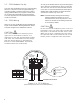
1.8 - 7231 Wiring
Wiring for the 7231 HT Modbus probe is illustrated in
Figure 4 and Installation Drawing E0242100, Sheet 1.
The probe is approved for hazardous locations.
CAUTION
Since the probe has an explosion proof
approval for hazardous locations, it is
important to use the appropriated conduit
and seals. All installations should comply
with the latest edition of The National
Electrical Code (ANSI/NFPA 70) and the
Canadian Electrical Code (CEC).
As many as 32 Modbus devices may be multi-dropped
on the same bus. A twisted pair is used to connect the
7231 to a host, such as a PC with a RS-485 converter
or PC card. It is recommended that the twisted pair be
shielded and at least 22 AWG. The shield should be
connected to common only at one end.
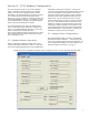
NOTE: If the RS-485 bus already has terminating
resistors installed, the jumper JP1 on the
motherboard must be set to position 2-3. This
will remove the built-in terminating resistor that
is connected by default.
CAUTION
Do not remove the explosion proof cover in a
hazardous area. You must make certain that
the power is locked out and the area is safe.
When servicing is completed, thcover must
be replaced and secured with the set screw
before power is applied to the instrument.