
Owner's manual


5
Dead
Band
2.75”
Span
Null
Zone
9.25”
Overall
Length
E-Clip
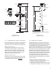
Typical Installation
Dead Band Spacer
Magnet Position
Product Level
Level Float
.625”Tube
Optional
Flange
.75” NPT Adjustable
Compression Fitting
Probe
Reducing
Bushing
Single Threaded
Connector
Magnet Position
Interface Level
Interface Float
4”
.75” NPT Conduit
Connection
Float Spacer
Probe Head
Probe Foot
Type Null Dead
Band
Overall
Length
316SS 9.25”
(235mm)
2.75”
(70mm)
21 to 288”
(533 to 7315mm)
2“ Bung
Dual Threaded
Connector
Reducing
Bushing
.75” NPT Conduit
Connection
Temp. 5
Temp. 4
Temp. 3
Temp. 2
Temp. 1
Probe Head
Probe Foot
12”
23.5” For High
Temp Applications*
Level Float
Interface Float
Dead Band 2.75”
Null Zone 9.25” *
Span
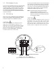
* For High-Temperature applications between 70-125 deg. C,
use a compression fitting 23.5” from the top of the enclosure
when installing the probe.
Overall
Length
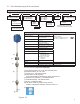
Figure 1.2
(Drawing not to scale.)
Figure 1.3
(Drawing not to scale.)
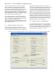
1.6 - Off-Set Procedure
Analog probes require you to assign a value to the
incremental change to the span from 4mA to 20mA.
The 7230 Series is a digital probe with high resolution
and repeatability, but the overall accuracy is also
dependant upon the installation set-up. The 7231/7235
position output is the actual position of the fl oat magnet
on the active area of the magnetostrictive wave guide.
While there is no calibration of the probe, you must
provide a reference point for the level measurement.
The probe output indicates the position of the magnet
on the probe, the instrument does not know where
it is located in the tank. The measurement of a
level change is extremely accurate, but to insure an
accurate absolute level measurement, the level may
require correction.
1. Measure the level of the tank manually.
2. Install the probe and compare the sensor’s level
position with the manual measurement.
3. If necessary, calculate the “offset” (correction factor
and apply this to the probe output in the controller.
1.5 - Temperature Sensor Locations
The 7230 Series probes come with 1 or 5 temperature
sensors. See Figure 3. The physical location of the
temperature sensors are based upon the probe span.
Single Temp Sensors
R1 probes have the temperature sensor located
12” from the foot of the probe. T1 probes have the
temperature sensor located 4” from the foot of the
probe. For R1 and T1 options, all temperature data
will be of just the one temperature sensor (i.e. all
temperature readings will be the same).
Multiple Temp Sensors
R5 probes have the fi rst temperature sensor located
12” from the foot of the probe. The distance between
each adjacent sensors is equal to Span-9.25”
5