
Owner's manual


4
1.4 - Installation of a Rigid Probe
The D style connector with dual 3/4 NPT thread does
not require a compression fi tting for installation. The S
style connector will require a compression fi tting, which
is mounted below the tube crimp on the probe to insure
a proper seal.
Assemble the Probe
(See Figure 1.1 on pg. 3)
1. Mount the Compression Fitting (a) if the Style S
connector is being used.
2. Install the bushing if it is used.
3. If the probe has 1 fl oat, (F1), slide the Level Float
(b) or Interface Float (d) onto the probe. If the probe
has 2 fl oats, (F2), slide the Level Float (b) onto the
probe, followed by the Float Spacer (c), and then
the Interface Float (d). The magnet is located in the
middle of the 316 SS Level Float, so orientation
does not matter. The 316SS Interface Float must be
positioned with the plates at the bottom.
4. Slide the Dead Band Spacer (e) onto the probe.
5. Capture these parts with either a retainer E-Clip (f)
or the End Cap (g).
6. Verify that the fl oats and spacers move smoothly up
and down the probe.
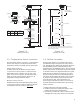
Insert the Probe
See Figure 1.2 on page 5
7. Insert the foot of the probe into the tank. Do not
allow the fl oat(s) to drop suddenly since this
could damage the fl oat or retainer at foot of the
probe.
8. Thread the bushing into the tank, fl ange, or bung/
riser. Properly fasten the bushing and fl ange.
9. Thread the compression fi tting or probe into the
bushing or fl ange.
10. Hand tighten. To insure Compression Fitting is
sealed, turn it 1 1/4 turns after hand tightening.
11. Make fi nal check to see that all fasteners are
in proper position and that the probe is securely
tightened.
1.2 - Mounting Conditions
1. The 7230 Series HT Digital Probe level system
is designed for industrial applications, but should
be mounted in a location as free as possible from
vibration, corrosive atmospheres, or any possibility
of mechanical damage.
2. Mount the probe in a reasonably accessible location,
away from agitation.
3. Process temperature is between -40°F and 257°F
(-40°C to 125°C).
4. Mount the probe perpendicular with gravity so the
fl oat moves freely along the probe.
CAUTION
When installing probes, do not bend rigid
probes. Permanent damage may result.
(Consult factory about a telescoping
support to assist with the installation of
20-24 ft. probes) Rigid probes, longer than
10 ft., need to be supported at both ends
while handling. Remove the Caution Tag
before installing. Probes are built with the
electronic circuits sealed inside the tube at
the factory. Do not attempt to open or weld
on the tube.
1.3 - Unpacking
Carefully remove the contents of the shipping carton
and check each item against the packing list before
destroying the packing materials. Any damage must be
reported to the shipping company. If you do not receive
all of the parts on the packing slip, contact Ametek
at 800-635-0289 (US and Canada) or 248-435-0700
(International).
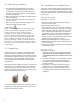
Most rigid probes are shipped in a Tube. To remove the
metal end cap, use a large, fl at blade screw driver or a
metal rod and tap on the inner edge of the cap until it
pivots. Grab the cap and pull it out. Use caution as the
edge of the metal cap may be sharp.
If you have an RMA warranty claim, pack the probe in a
shipping tube or with stiff reinforcement to prevent the
probe from being bent in transit.