
Owner's manual


18
For probes ordered with only 1 temperature sensor (i.e.
T1 or R1), a temperature reading is taken on that one
temperature sensor and that value is placed in all fi ve
temperature data locations in the string.
NOTE: Data values outside the ranges specifi ed above
indicate an error condition.
A value of “999.9999” will be transmitted if there is
an error in the product or interface levels. A value of
“-999.9” will be transmitted if there is an error in the
temperature sensor measurement.
Calculation of Checksum
All characters (from and including the start character
(‘^’) to and including the comma (‘,’) after the fi nal
temperature digit) in the data string are added up to a
byte (8-bit) value. Take the upper nibble (4-bits) and
lower nibble (4-bits) of that byte and convert each
nibble value to its equivalent ASCII character.
For example:
If all the characters add up to 0xA5 (hex); it would
transmit an ‘A’ and a ‘5’ char to represent the upper and
lower nibble values. The 2-digit ASCII checksum (CC)
would be: 0x41 0x35 (or the ASCII equivalent chars ‘A’
‘5’).
Data Transmission Example
The following example represents the data transmitted
from a 7235 HR Digital Stik.
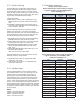
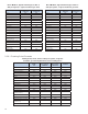
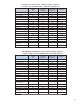
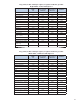
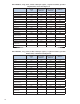
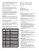
The following example represents a full transmission
data string (139 bytes) from a 7235 HR Digital Stik
probe with the following information (Bytes 0 - 135 are
used to compute the checksum):
NOTE: The Level data in the following chart may not
be representative of a valid product level. The data is
for demonstration purposes only.
Data Transmission
Byte #s ASCII Chr
String
Level Name
0-1 ^, Start Character
2-10 123.4567, Product 1
11-19 456.7890, Product 2
20-28 654.3212, Product 3
29-37 987.6543, Product 4
38-46 124.5789, Product 5
47-55 234.5678, Product 6
56-64 267.4310, Product 7
65-73 478.2354, Product 8
74-82 752.6143, Product 9
83-91 891.4578, Product 10
92-100 002.5389, Interface 1
101-107 +122.1, Temperature 1
108-114 +122.3, Temperature 2
115-121 +122.5, Temperature 3
122-128 +122.3, Temperature 4
129-135 +122.1, Temperature 5
136-137 CC 2-digit ASCII Checksum
138 <cr> Carriage Return
Section 4 - Basic Trouble
Shooting: 7230 HT Series
Magnetostrictive Probes
Symptoms:
No Signal
Intermittent Signal
Erratic Temperature reading
Faulty water level measurement
Faulty product level measurement
Diagnostics:
1. Check error codes for 7231 HT Modbus probe
• Error Codes (page 10)
a) Value of 2000 in the product, interface or
temperature registers indicates a loss of signal.
b) Value of 1000 in the product or interface register
indicates a communication problem or a “dead”
probe.
2. Check error codes for 7235 HT Digital probe
• Error Codes (page 18)
a) 999.9999 error of signal for product or interface
level.
b) -99.9 error of signal from temperature sensor.
(see page 18)
3. Locating the Problem Source
• Is the problem with the probe or elsewhere?
Connect a working (or demo) probe from another
tank to confi rm that the problem is related to the
probe and not the wiring or communications.
• Does the wiring (ground and signal) and power
meet the specifi cations? If not, you can have
erratic or complete loss of signal.
• Has the PLC/controller been setup properly to work
with this probe?
4. Floats
• Are the correct number of fl oats being used?, F1 is
one fl oat, F2 is two fl oats.
• Are the fl oats correctly installed? The product fl oat
must be positioned above the Interface (water)
fl oat.
• Were the fl oats supplied (or evaluated) by APT?
Internal magnet must match probe.
• Are the fl oats “sticking” or moving freely? No
build-up on probe.
• Are the magnets in the product and interface fl oats
4 inches apart on a long probe?
5. Magnetic Fields
• Was the head of the probe accidentally
magnetized? This can be done in the fi eld and can
cause signifi cant problems. Degauss the head of
the probe.
• Is there a magnet fi eld in the tank? Pull the probe
partially out of the tank about 2 ft to see if the
problem is resolved.
6. Unexpected Readings
• Confi rm actual levels and temperature reading
directly from Probe. Compare these to known
values. This can be done manually in the fi eld.
Make sure that temperature sensors located
outside of the liquid are not being used to calculate
an average.
.