
Owner's manual


17
Section 3 - 7235 ASCII Digital
Set Up and Wiring
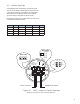
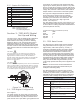
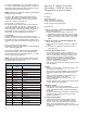
The wiring for the 7235 HT Digital probe is illustrated
in Figure 5 and connects to a standard terminal
block located in the housing as shown in Drawing
E0242100, Sheet 2. The 7235 is also approved for
hazardous locations, so it is important to use the
appropriate conduit and seals. The recommend cable
is a three conductor with shield, Belden# 6501FE, 22
AWG and the maximum recommended cable length is
150 feet.
CAUTION
Since the probe has an explosion proof approval
for hazardous locations, it is important to use the
appropriated conduit and seals. All installations
should comply with the latest edition of The National
Electrical Code (ANSI/NFPA 70) and the Canadian
Electrical Code (CEC).
CAUTION
Do not remove the explosion proof cover in a hazardous
area. You must make certain that the power is locked
out and the area is safe. When servicing is completed,
the cover must be replaced and secured with the set
screw before power is applied to the instrument.
DATAPWR COM
3.1 - 7235 Digital Confi guration
Data Signal
The “Data” signal is an “open-drain” type signal and
is used for the bidirectional half duplex asynchronous
serial communications. Any device connected to the
probe must be of an “open-drain” type signal and must
not be driven to a high logic level. Because this data
signal may be driven by either the master or any slave
device, a single pull up resister of typically 1kΩ should
be the only element that establishes the high logic level
voltage. Also, because of this scheme, there could be
multiple master or slave devices connected together.
The logic level voltage thresholds are similar to TTL
levels and a pull-up resistor must be included in
the user’s interface circuitry. This signal is clamped
internally by the 7235 with a +5V TVS device. The
inactive or “idle” state is at a “high” logic level.
Power Consumption
The 7235 draws roughly 13mA of current when it is not
taking temperature measurements and roughly 15mA
of current when it is taking temperature measurements
(with 5 temperature sensors).
Communication Parameters (fi xed)
baud 9600
parity odd
data bits 7
start bits 1
stop bits 1
3.2 - 7235 Data Format
The data string is in ASCII format and the total data
string transmission time is roughly one (1) second.
Approximately 100ms after power up, a carat (‘^’)
character is transmitted and the fi rst product position
is measured and transmitted. Subsequent position
measurement and transmission continues every
100ms until 10 products have been transmitted. One
interface position is transmitted immediately following
the 10th product position. All temperature data is then
transmitted along with a fi nal 2-digit ASCII Checksum
followed by a Carriage Return character to end the
string. This whole data string transmission process
continuously repeats itself while power is applied to the
probe.
NOTE: A comma character is transmitted between
each position and temperature measurement (see
example in Data String table).
The data string length is 139 bytes total. The data
string is comprised of a carat (‘^’) character (i.e. start
character), 10 product levels, 1 interface level, and 5
temperature sensor levels followed by a 2-digit ASCII
Check sum and a carriage return character (<CR>).
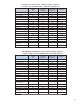
Data String
^,ppp.pppp,ppp.pppp,…
...,ppp.pppp,iii.iiii,+/-ttt.t,…,+/-ttt.t,CC<cr>
^: Start Character
(identifi es protocol, type and quantity of following data)
ppp.pppp: Product
(000.0000” to 600.0000”)
iii.iiii: Interface
(000.0000” to 600.0000”)
(NOTE: Interface = 000.0000 if Stik is ordered with only
1 fl oat)
+/-ttt.t: Temperature
(-40.0
º
C to +125.0
º
C)
CC: 2 digit ASCII checksum
(see calculation of checksum below)
<cr>: End of data string - carriage return
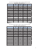
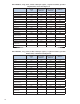
Common values:
Status = 256 indicates magnet error
Status = 32768 indicates 7231 HT
not communicating with probe
Bit Defi nition
0-7 Reserved
8 Magnet missing/ Fault with Product or Interface
9 Temperature 1 Fault
10 Temperature 2 Fault
11 Temperature 3 Fault
12 Temperature 4 Fault
13 Temperature 5 Fault
14 Span (Probe Length)
15 Not connected to probe
16-31 Reserved
2.17 - Status Bit Defi nitions
Figure 3.1 - 7235 Wiring