
Owner's manual


9
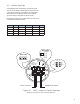
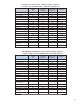
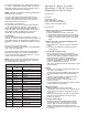
2.5 - Jumper Settings
In the Modbus slave confi guration, jumpers JP2 and
JP3 control the Modbus format (RTU or ASCII) and the
communication settings, according to the chart below.
The Data bits for the Down position of JP3 depend
upon the setting of JP2 (RTU or ASCII format).
Note these jumpers have no effect when the 7231 HT is
confi gured as a Modbus master.
JP2 JP3 Mode Data bits Stop bits Parity
*Up *Up RTU 8 1 None
Up Down RTU 8 1 Even
Down Up ASCII 8 1 None
Down Down ASCII 7 1 Even
0
1
2
3
4
5
6
7
8
9
0
1
2
3
4
5
6
7
8
9
0
1
2
3
4
5
6
7
8
9
0
1
2
3
4
5
6
7
8
9
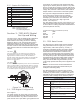
DM231
Status LED
Power /
4-20 mA Converter
Status LED
MODBUS RTU/ASCIIPower 9-30 VDC
0
1
2
3
4
5
6
7
8
9
0
1
2
3
4
5
6
7
8
9
0
1
2
3
4
5
6
7
8
9
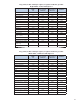
100’s 10’s 1’s
Device ID
Baud Rate
0 - 19200 Master Modbus
4-20m Module
1 - 600 bps
2 - 1200 bps
3 - 2400 bps
4 - 4800 bps
5 - 9600 bps
6 - 14400 bps
7 - 19200 bps
8 - 38400 bps
9 - 57600 bps
0
1
2
3
4
5
6
7
8
9
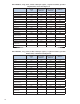
JP2 JP3
Down
Up
Down
Up
}
}
{
{
Figure 2.1 - 7231 Jumper & Switch Settings
* Default Setting
(Switches and jumpers shown in the default positions.)