Series 7230 INSTALLATION & OPERATING MANUAL CONTINUOUS LEVEL CONTROLS 7230 HT Series Digital Probe MAGNETOSTRICTIVE LEVEL SYSTEM ABSOLUTE PROCESS CONTROL KNOW WHERE YOU ARE...
.
7230 Ht Series Digital Probe Installation & Operating Manual Table of Contents Section 1 - 7230 Series HT Digital Probe ...........................................................................2 1.1 - Part Numbering and Accessories........................................................................3 1.2 - Mounting Conditions............................................................................................4 1.3 - Unpacking.......................................................................
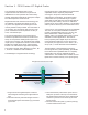
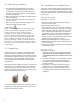
Section 1 - 7230 Series HT Digital Probe The 7230 Series HT Digital Probe is a new magnetostrictive level measurement system from AMETEK APT for the up-stream Oil & Gas Industry and high temperature applications that require multiple level and temperature measurements. Magnetostrictive level measurement technology has the capability of providing the highest accuracy of any of the most popular level technologies that are currently offered in today’s market.
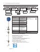
1.1 - Part Numbering and Accessories Part Numbering 723 X X X X LLL Protocol 1 = Modbus 5 = Proprietary ASCII Fx # of Temp Points R1 = 1 Sensor R5 = 5 Sensors T1 = 1 Sensor Connector Style D = 3/4” NPT Dual S = 3/4” NPT Single 7230 Series HT Digital Probe Rx Fittings E = English M = Metric** H EX Special Mounting EX = FM (US & Canada) Overall Length* Mounting Style H = Condulet # of Floats F1 = 1 Float F2 = 2 Floats * Specified in whole 1” increments. See Dimension Drawing for ranges.
1.2 - Mounting Conditions 1.4 - Installation of a Rigid Probe 1. The 7230 Series HT Digital Probe level system is designed for industrial applications, but should be mounted in a location as free as possible from vibration, corrosive atmospheres, or any possibility of mechanical damage. 2. Mount the probe in a reasonably accessible location, away from agitation. 3. Process temperature is between -40°F and 257°F (-40°C to 125°C). 4.
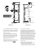
.75” NPT Conduit Connection Probe Head Probe Head 4” Null Zone 9.25” * Single Threaded Connector .75” NPT Conduit Connection 23.5” For High Temp Applications* Probe Dual Threaded Connector Reducing Bushing .75” NPT Adjustable Compression Fitting Reducing Bushing Null Zone 9.25” Temp. 5 Optional Flange Overall Length 2“ Bung Temp. 4 Level Float .625”Tube Level Float Overall Length Product Level Null 316SS 9.25” (235mm) Dead Band 2.
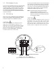
1.7 - 7231 Modbus Set Up As many as 32 Modbus devices may be multi-dropped on the same bus. A twisted pair is used to connect the 7231 to a host, such as a PC with a RS-485 converter or PC card. It is recommended that the twisted pair be shielded and at least 22 AWG. The shield should be connected to common only at one end. The 7231 uses the Modbus protocol for communicating with a PC or devices such as a programmable logic controller. Modbus is a master-slave protocol that is openly published.
Section 2 - 7231- Modbus Configuration The 7231 HT has 2 modes: it can act as a Modbus slave, responding to data requests from a Modbus master, or it can act as a Modbus master, used for interfacing to an optional Modbus to 4-20 mA converter. The mode is determined by the Baud Rate switch (figure 4.1 on pg. 9). Position 0 configures the 7231 HT as a Modbus Master. Positions 1- 9 configure the 7231 HT as a Modbus Slave, and also sets the baud rate at which it will communicate with the master.
2.3 - Modbus Slave Operation When configured as slave, the 7231 HT responds to requests for data from a Modbus master. The data available is the product, interface, total covered temperature, product temperature, interface temperature, span (probe length), max temperature, and the individual values of the 5 temperature sensors from the probe as well as the status of the probe. The 7231 HT is capable of communicating using the Modbus RTU or ASCII format. The format is selected by the on board jumper JP2.
2.5 - Jumper Settings In the Modbus slave configuration, jumpers JP2 and JP3 control the Modbus format (RTU or ASCII) and the communication settings, according to the chart below. The Data bits for the Down position of JP3 depend upon the setting of JP2 (RTU or ASCII format). Note these jumpers have no effect when the 7231 HT is configured as a Modbus master.
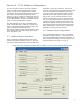
2.6 - Data Points 2.10 - Enron Modbus The data points available are: Enron Modbus has a few differences from Traditional Modbus. One difference is the register offsets follow a different numbering scheme, with integer values residing in the 3XXX range, long integers in the 5XXX range, and floating points in the 7XXX range. The second difference is that 32 bits of data can be returned in one register. The 7231 HT supports both of these features, by selection of the proper register value.
2.13 - Byte Ordering In the Modbus slave configuration, data can be accessed as integers (16 bits), long integers (32 bits), and floating point value (32 bits). The order that the bytes are sent must be known by the master in order to assembly the bytes into the correct value. Byte ordering can have a few different terminologies. 1) Big/Little Endian. 2) Byte order by number, with 1 indicating the most significant part of the value, and 4 the least significant.
Enron Modbus, Signed 16 bit Integer, 16 bits of data per register, 1 register needed to get value Data Big Endian/ Hi Byte first Little Endian/ Low Byte first Product 3002 3202 Interface 3004 3204 Enron Modbus, Signed 16 bit Integer, 16 bits of data per register, 1 register needed to get value Data Big Endian/ Hi Byte first Little Endian/ Low Byte first Product 3102 3302 Interface 3104 3304 product temperature 3006 3206 product temperature 3106 3306 interface temperature 3008 3208
Floating Point, 32 bit, 16 bits of data per register, 2 registers needed to get value Metric Units, centimeters and degrees C Data Product Big Endian/ HWHB/ 1234 Little Endian/ Byte Swapped/ LWHB/3412 Big Endian/ Byte Swapped/ HWLB/2143 Little Endian/ LWHB/4321 30303 30503 30703 30903 Interface 30305 30505 30705 30905 product temperature 30307 30507 30707 30907 interface temperature 30309 30509 30709 30909 average temperature 30311 30511 30711 30911 status 30313 30513 30713
Enron Modbus, Floating Point, 32 bit, 32 bits of data per register, 1 register needed to get value Metric Units, centimeters and degrees C Data Big Endian/ HWHB/ 1234 Little Endian/ Byte Swapped/ LWHB/3412 Big Endian/ Byte Swapped/ HWLB/2143 Little Endian/ LWHB/4321 Product 7002 7202 7402 7602 Interface 7004 7204 7404 7604 product temperature 7006 7206 7406 7606 interface temperature 7008 7208 7408 7608 average temperature 7010 7210 7410 7610 status 7012 7212 7412 7612 Spa
Long, 32 bit, 16 bits of data per register, 2 registers needed to get value English Units, inches and degrees F Data Big Endian/ HWHB/ 1234 Little Endian/ Byte Swapped/ LWHB/3412 Big Endian/ Byte Swapped/ HWLB/2143 Little Endian/ LWHB/4321 Product 31003 31203 31403 31603 Interface 31005 31205 31405 31605 product temperature 31007 31207 31407 31607 interface temperature 31009 31209 31409 31609 average temperature 31011 31211 31411 31611 status 31013 31213 31413 31613 Span
Enron Modbus, Long, 32 bit, 32 bits of data per register, 1 register needed to get value English Units, inches and degrees F Data Big Endian/ HWHB/ 1234 Little Endian/ Byte Swapped/ LWHB/3412 Big Endian/ Byte Swapped/ HWLB/2143 Little Endian/ LWHB/4321 Product 5002 5202 5402 5602 Interface 5004 5204 5404 5604 product temperature 5006 5206 5406 5606 interface temperature 5008 5208 5408 5608 average temperature 5010 5210 5410 5610 status 5012 5212 5412 5612 Span 5014 5214
2.
For probes ordered with only 1 temperature sensor (i.e. T1 or R1), a temperature reading is taken on that one temperature sensor and that value is placed in all five temperature data locations in the string. Section 4 - Basic Trouble Shooting: 7230 HT Series Magnetostrictive Probes NOTE: Data values outside the ranges specified above indicate an error condition. Symptoms: A value of “999.9999” will be transmitted if there is an error in the product or interface levels. A value of “-999.
19 Clawson, MI 48017 U.S.A.
20 Clawson, MI 48017 U.S.A.
21 COM DATA Clawson, MI 48017 U.S.A.
Notes Part Number Serial Number Purchase Order Number Sales Order Number Comments Section 5 - Equipment Return Contact your Distributor before returning equipment to the factory. In order to provide prompt and reliable service, any equipment being returned for repair or credit, must be preapproved by the factory. For all UPS shipments, notify your driver and the UPS office immediately. You must file a claim with UPS as soon as possible. Then advise H&R Mfg. and Supply for reshipment, etc.
. Other Products Copyright 2008 by AMETEK AUTOMATION & PROCESS TECHNOLOGIES. All Rights Reserved. 1080 N. Crooks Road, Clawson, MI 48017-1097 Phone: 248-435-0700 Toll Free: 800-635-0289 Fax: 248-435-8120 www.ametekapt.com 7230.M3R 3/09.