Series 2120 Series 956 INSTALLATION MANUAL RESOLVER & LDT INTERFACING 2120 PLC Interface Module ABSOLUTE PROCESS CONTROL KNOW WHERE YOU ARE... REGARDLESS 2120 Manual Z71.
1080 North Crooks Road Clawson, MI 48017-1097 Phone: (248) 435-0700 FAX: (248) 435-8120 Internet: www.ametekapt.com www.ametek.com Preface This manual is divided into four parts. Part 1 provides an introduction for the Theory and Operation of the Series 2120 PLC Interface Module. Part 2 contains a Hardware Overview. Part 3 explains the Mounting and Wiring of the 2120 PLC Interface Module. Part 4 provides the Programming Instructions.
Contents Chapter 1: Theory of Operation 1 Chapter 2: Hardware Overview 2 2.1 Standard Modules ..................................................................................................................... 3 Controller (FMMP01) ......................................................................................................... 3 Power Supply (FMPS01) .................................................................................................... 3 2.2 Input/Output Module .................
.2 : LDT Configuration Functions..........................................................................................27 Wire Speed (300) .............................................................................................................. 28 Count Direction (301) ....................................................................................................... 28 Position Offset (302) .........................................................................................................
Chapter 1: Theory of Operation Chapter 1: Theory of Operation The Gemco Series 2120 PLC Interface Module converts the input signal from a resolver based rotary transducer or Magnetostrictive Linear Displacement Transducer (LDT) to digital analog or overtravel relay outputs. Resolver based inputs provide up to 14 bit resolution per turn with a field programmable scale factor. LDT based inputs allow field selection of position data in inches to .001 inches or millimeters to .01 millimeter.
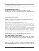
Chapter 2: Hardware Overview Chapter 2: Hardware Overview This chapter contains descriptions of the Interface Module’s components. For installation instructions, see Chapter 3: Mounting and Wiring. The Interface Module contains a heavy-duty case which can hold up to five modules. Several optional modules can be used with the Interface Module. See also Appendix C: Catalog Numbering System for more information on optional modules.
Chapter 2: Hardware Overview 2.1: Standard Modules This section provides descriptions of basic Interface Modules (also see Section 2.2: Input/Output Modules). Controller (FMMP01) This module contains the Central Processing Unit (CPU) which is used to process data it receives from the resolver or Linear Displacement Transducer (LDT). It then shows the position on the Interface display. The controller is also responsible for continuously monitoring all programmed setpoints and timing functions.
Chapter 2: Hardware Overview Variable Pulse (FMIP01) Input Option V1 This module is used with an LDT that provides its output in the form of a pulse width modulated RS-422 signal. This module only works with Gemco Series 951VP2110 LDT’s. LDT Input (FMIP02) Input Option L1 This module will accept an output from a controlled pulse, start stop pulse or variable pulse magnetostructive LDT. This card accepts a wide range of LDT inputs and provides faster updates than the variable pulse version described above.
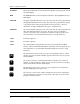
Chapter 2: Hardware Overview Relay Output (FMOR01) This optional module contains two overtravel limit relays. These relays can be programmed to either energize or deenergize upon reaching the programmed overtravel position. These relays will also actuate upon detection of the system and operating errors listed in chart A-5 in Appendix A. 2.3: Status LEDs Defined The Interface Module has 10 status LEDs and four programming keys.
Chapter 2: Hardware Overview POSITION This position LED turns on when the Interface Module is showing position in the large LED display. RPM The RPM LED turns on when the Interface Module is showing RPM in the large LED display. UPR LIM The upper limit LED reflects the state of the relay when the value programmed in the Upper End Limit function is reached. The relay can be programmed to energize or deenergize upon reaching the programmed overtravel position.
Chapter 3: Mounting and Wiring Chapter 3: Mounting and Wiring This chapter provides instructions for mounting and wiring the PLC Interface Module. These instructions have been divided into two sections: Section 3.1: Mounting and Section 3.2: Wiring.
Chapter 3: Mounting and Wiring 5. Insert each #6-32 UNC screw into each of the module’s screw holes. 6. Using a 7/64" Allen wrench, secure the screws into position. This will secure the mounting rails. 8 to 10 inch pounds of torque is required. Cabling The signals from a resolver or LDT are inherently very immune to electrical noise.
Chapter 3: Mounting and Wiring ALUMINUM BEZEL 6.00 5.32 CASE WIDTH 3.00 2.00 TYP PROGRAM FLT OK MVT FLT POSITION RPM UPR LIM LWR LIM AUX 1 AUX 2 AUX 3 SERIES 2120 F( ) 6.50 ALUMINUM CASE 3/8 DIN STD MOUNTING RAIL W/ FOOT 5.53 .50 2.61 MOUNTING RAIL FOOT MOUNTING SCREWS DEPLUGGABLE TERMINAL STRIPS 1/8" GASKET RECOMMENDED PANEL CUTOUT 2.67 5.
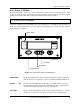
Chapter 3: Mounting and Wiring 3.2: Wiring This section contains pinout diagrams for each module. System wiring diagrams follow. Controller Module (FMMP01) The controller has two connectors: a D9 connector (J1) for RS-232 and RS-485 serial communications, and a program lockout connector (J2) intended for a keyswitch. (See Figure 3-2). Making connections to both connectors is optional. However, the program lockout connector must be jumpered to allow the unit to enter program mode.
Chapter 3: Mounting and Wiring RELAY RELAY 2 LOWER LIMIT { { 1 2 3 4 5 6 7 8 RELAY 1 UPPER LIMIT NO NO NC NC NO NO NC NC FMOR01 Figure 3-3 Relay Output Pinout Diagram Power Supply Module (FMPS01) The power supply module has a main power input, an auxiliary input, and a fault check output. (See Figure 3-4). Power input: 85-265 VAC at 450 mA maximum. Fault check output: 8 amps 250 VAC, 30 VDC, 1/4 HP 125, 250 VAC.
Chapter 3: Mounting and Wiring Resolver Module (FMIR01) The resolver module has an eight-position connector. (See Figure 3-5). The terminal wire size for all positions is No. 22-12 AWG. The reset-to-preset input is an edge sensitive input that resets position data to a preprogrammed value. An open collector sinking device or dry contact applied to these terminals activates the input. For programming of reset-to-preset value, see Chapter 4: Programming.
Chapter 3: Mounting and Wiring LDT Input (FMIP02) Input Option L1 This module will accept an output from a controlled pulse, start stop pulse or variable pulse magnetostrictive LDT. (See Figure 3-7). This card accepts a wide range of LDT inputs and provides faster updates than the variable pulse module as described on page 12. The pulse width signal is converted to position data which the monitor displays. The module also provides +24 VDC to supply power to the LDT.
Chapter 3: Mounting and Wiring PIN DIRECTION DESCRIPTION 1 2 3 4 5 6 7 8 OUT OUT OUT OUT OUT OUT OUT OUT DATA OUT BIT 0 DATA OUT BIT 2 DATA OUT BIT 4 9 10 11 12 13 14 OUT OUT OUT IN IN OUT DATA OUT BIT 16/INCREMENTAL OUT A* 15 16 17 OUT OUT OUT 18 19 20 21 22 23 24 25 OUT OUT OUT OUT OUT OUT IN IN DATA OUT BIT 6 DATA OUT BIT 8 DATA OUT BIT 10 DATA OUT BIT 12 DATA OUT BIT 14/INCREMENTAL OUT Z* PIN13 PIN25 D G T L DATA OUT BIT 18/INCREMENTAL OUT B BUSY* BUS ENABLE* GND DATA OUT BIT 1 DATA OUT
NO NO L1 L2 L1 L2 NO NO NC NC NO NO NC NC Installation and Programming Manual RELAY 1 2 3 4 5 6 7 8 INPUT+ OR PROGRAM (CLOSED) INPUT- SWITCH CLOSED ENABLES PROGRAM MODE DIAGRAM 1 8A 250VAC 30VDC 1/4 HP 125, 250VAC UPPER & LOWER LIMIT RELAY CONTACT RATINGS : LOWER LIMIT UPPER LIMIT FAULT CHECK RELAY CONTACT RATING : 8A 250VAC 30VDC 1/4 HP 125, 250VAC 4 FMOR01 R E L A Y GND CHASSIS RXD RS-232 TXD RS-232 NO CONNECTION GND SIGNAL TX2+ RS-485 RTS RS-232 CTS RS-232 TX2- RS-485 1 2 3 4 5 6 7 8 9
16 NO NO L1 L2 L1 L2 NO NO NC NC NO NO NC NC Installation and Programming Manual Figure 3-11 LDT - Based System Wiring Diagram SEE NOTE 1 + OPTIONAL CUSTOMER DC POWER SUPPLY 5-24VDC 6mA MAX.
NO NO L1 L2 Installation and Programming Manual + OPTIONAL CUSTOMER DC POWER SUPPLY 5-24VDC 6mA MAX. - 8A 250VAC 30VDC 1/4 HP 125, 250VAC FMIP02 PROBE FM1P01 PROBE RELAY 2 RXD RS-232 TXD RS-232 NO CONNECTION GND SIGNAL TX2+ RS-485 RTS RS-232 CTS RS-232 TX2- RS-485 2 3 4 5 6 7 8 9 INPUT+ INPUT- SINKING DEVICE, +5VDC MAX ON AT < 1VDC @ 0.2mA PROGRAM SECURITY INSULATE AND TIE BACK ALL UNUSED WIRES PROBE CONN.
Chapter 3: Mounting and Wiring PIN25 POWER POWER SUPPLY 4 PIN13 3 RELAY 2 RSLVR C.P.U.
Chapter 3: Mounting and Wiring 5 TO 24 VDC - DIGITAL OUTPUT MODULE OUTPUT RATING: SINKNG DEVICE, 5 TO 24 VDC 100mA MAX GND CUSTOMER DC POWER SUPPLY + COM 13 DIGITAL OUTPUTS DATA 0-19, BUSY { ALLEN BRADLEY 1771.
POWER 4 4 REFER TO MANUAL FOR CORRECT SLOT LOCATION BEFORE INSTALLING MODULE POWER FMPS01 }FLT CHK }AUX INP GND L2 L1 100-240VAC 50/60HZ 1 2 3 4 5 6 7 3 3 2 2 ANALOG 1 2 3 4 5 6 7 8 Fig 3-14 Wiring Diagram Analog Output Drawing E8005090 Installation and Programming Manual FMOA01 1 1 FMMP01 C.P.U.
Chapter 4: Programming Chapter 4: Programming This chapter provides detailed descriptions and instructions for programming all Interface Module’s functions. A complete list of functions (with brief explanations) can be found in Appendix B: Function Summary Chart. This chapter divides the functions into the following seven sections. 4.1 Resolver Input Configuration Functions 4.2 LDT Configuration Functions 4.3 Monitor Setup Functions 4.4 Relay Setup Functions 4.5 Digital Outputs 4.6 Analog Outputs 4.
Chapter 4: Programming Figure 4-1 calls out the Interface Module’s programming keys. Following this figure are descriptions of these keys and how they work, as well as, a short tutorial on how to use the keys. Status LEDs PROGRAM FLT OK MVT FLT POSITION RPM UPR LIM LWR LIM AUX 1 AUX 2 AUX 3 SERIES 2120 F( ) Enter Key Shift Key Scroll Key Function Key Figure 4-1 Programming Keys Programming Keys Defined The Interface Module has four keys located on the front panel.
Chapter 4: Programming The shift key is used to move to a specific digit shown on the Interface Module’s LED display. This can be done to either select a function number or a value for a function. To move to a specific digit on the display, select the function key and then the shift key. The right-most digit will then flash. This indicates that the digit is activated to be incremented. (To increment the digit, select the scroll key.) Continue to select the shift key until the desired digit is activated.
Chapter 4: Programming Turns Counting Wrap Around (308) When using the Turns Counting software described above where the Turns Count Function (301) is set for 2 or more, you have the option of selecting the Wrap Around feature. Under normal operation, you select a scale factor using function 300 followed by the number of turns required to reach the selected scale factor using function 301.
Chapter 4: Programming NOTE: The Interface Module is defaulted to stay in program mode for 120 seconds. The monitor will drop out of program mode if a key is not pressed within this time. If this occurs, you will have to repeat steps 1-3. Further, the access code (2100) is provided initially. This code can be changed through the use of the New Access Code function. For security reasons, this function can only be implemented when the monitor is in supervisory mode.
Chapter 4: Programming Program Position Offset (302) (F) 13. Select the function key. The monitor displays “F----”. 302 Enter desired reading 14. Select function number 302 (Position Offset Function). Select the enter key. The monitor displays the current position. 15. Enter the actual or desired machine position reading. Select the enter key. After configuring the encoder module for use with a resolver, you can proceed to Section 4.3: Monitor Setup functions.
Chapter 4: Programming Enter Desired Position 21. Enter desired Reset Value. Select the enter key. NOTE: If 301 is set to 0, the Reset Value must be less than the Scale Factor. 4.2: LDT Configuration Functions There are two input cards available for use with LDTs. 1. Specified as option V1 in the part number and is labeled (FMIP01) on the card. 2. Specified as option L1 in the part number and is labeled (FMIP02) on the card.
Chapter 4: Programming Wire Speed (300) Programming of the wire speed synchronizes the performance of the module with the performance of the LDT. You will find the wire speed on the legend plate of your LDT. To program wire speed, perform the following steps: (F) 1. The monitor displays “F-----”. 300 2. Enter new value Select the function key. Select function number 300. Select the enter key. The monitor displays the current wire speed. 3. Enter the new wire speed value.
Chapter 4: Programming Count Direction Function = 0 Count Direction Function = 1 100 0 When the Count Direction Function is programmed with a value of 0, the display value will increase when the LDT’s magnet assembly is moving away from the head of the LDT. 100 When the Count Direction Function is programmed with a value of 1, the display value will increase when the LDT’s magnet assembly is moving toward the head of the LDT.
Chapter 4: Programming Fault Pulse Time (306) Most magnetostrictive LDTs send out a fault pulse during a fault condition. The series 2120 Interface Module is preset for use with all Gemco LDT products. The Fault Pulse Time function is used to program the pulse time of the fault signal sent by an LDT not manufactured by Gemco. When the monitor receives a fault signal of this pulse time, it will indicate an error (see Appendix A: Error Messages). The default for this function is 10 microseconds.
Chapter 4: Programming After configuring the Interface Module for use with an LDT, you can proceed to Section 4.3: Monitor Setup Functions. LDT L1 Input Reset-to-Preset (311) The reset-to-preset input is an edge sensitive input that resets position data to a preprogrammed value. A 5-24VDC source applied to these terminals activates the input. (F) 1. The monitor displays “F----”. 311 2. Enter desired value Select the function key.
Chapter 4: Programming (F) 1. The monitor displays “F-----” 14 2. Enter function number 14. Select the enter key. The monitor displays the function’s current value. Enter either 0 or 1 Select the function key. 3. Enter either 0 or 1. Select enter key. NOTE: If you change the unit of measurement, the decimal location shown on the monitor’s LED display will change to the default position for the unit of measurement selected.
Chapter 4: Programming used for the Position Hold dwell time. The position hold dwell time is the amount of time the monitor continues to hold the displayed position after the auxiliary input is released (or activated, depending on the input’s programmed state). To enable or disable the Position Hold function, perform the following steps: (F) 1. The monitor displays “F-----” 15 2. Enter either 0, 1, or 2 Select the function key. Enter function number 15. Select the enter key.
Chapter 4: Programming (F) 16 Enter either 0 or 1 The monitor displays “F-----” 2. Select function number 16. Select the enter key. The monitor displays the function’s current value. 3. Enter either 0 or 1. Select the enter key. Move Detection Time-out (12) The Move Detection feature is used to monitor the time between when a signal is sent to initiate machine movement and when movement is actually detected. The default value for this function is 5.00 seconds. This value can range from 0 to 99.
Chapter 4: Programming To put the monitor in program mode, see Program Mode Access in Section 4.7: Program and Supervisory Mode Functions. The following is a list of the press setup functions: Upper End Limit (400) Lower End Limit (401) Relay State (402) Relay Override (403) Upper End Limit (400) The Upper End Limit function is used to program the position value at which the upper end limit relay actuates.
Chapter 4: Programming Enter lower end limit The monitor displays the function’s current value. 3. Enter the new value. Select the enter key. NOTE: To temporarily override the lower end limit relay, see Relay Override. Relay State (402) The Relay State function is used to program the Interface Module’s upper and lower limit relays to either energize or de-energize when their programmed value is reached or exceed. Either a 0 or 1 can be programmed in this function.
Chapter 4: Programming NOTE: After overriding either the upper or lower limit relays, the operator should move the machine back into its normal operating range between its upper and lower limits. If the machine is again moved in the wrong direction (towards the limits), the upper or lower limit relays will again actuate. Step 1 - 3 will have to then be repeated. 4.
Chapter 4: Programming 201 2. Enter either 0 or 1 Enter function 201. Select the enter key. The monitor displays the function’s current value. 3. Enter either 0 or 1. 0 = Latch (default) 1 = Synchronize Select the enter key. Logic Level (202) This function will set up selection of either high true or low true logic. (F) 1. Select the function key. The monitor displays “F-----” 202 Enter either 0 or 1 2. Enter function 202. Select the enter key.
Chapter 4: Programming 4.6: Analog Outputs The Analog Output board provides two channels of analog output that can be independently configured and scaled. Each channel can be configured for an output based upon position or velocity. Velocity will be RPM if the sensor is a resolver or inches/mm per second if the input sensor is an LDT. The two channels of analog output allows you to configure one analog output to be based on position while the other channel provides a simultaneous indication of velocity.
Chapter 4: Programming (F) B) Select voltage or current output 1. Select the function key. The monitor displays “F-----” X04 2. Enter function number X04. Select the enter key. The monitor displays the current function value. Enter 0 or 1 0 = voltage output 1 = current output 3. Leave current value or change. Select enter key.
Chapter 4: Programming X02 Enter 000500 (F) 4. Enter function number X02. Select enter key. The monitor displays current minimum RPM value. 5. Enter 500. Select enter key. This sets minimum RPM value at 500 RPM. The monitor displays 000500. 6. Select function key. The monitor displays “F----”. X05 Enter 002000 (F) 7. Enter function number X05. Select enter key. The monitor displays current voltage output value linked to minimum RPM value. 8. Enter 2. Select enter key.
Chapter 4: Programming Analog output channel 1 will now provide a 2 to 8 VDC output as RPM increases between 500 and 2000 RPM. RPM values below 500 RPM will result in a 2 VDC analog output. RPM values above 2000 RPM will result in an 8 VDC output. Analog output channel 2 is programmed using the same basic sequences except with the function numbers noted below. Remember that the X shown in the function number represents the slot in which the analog output board is installed in the Interface Module chassis.
Chapter 4: Programming 4.7: Program and Supervisory Mode Functions This section provides descriptions and instructions for program and supervisory mode functions. These functions are used to put the Interface Module in either program or supervisory mode, as well as, program the length of programming time and change the program mode access code. Before a function can be programmed, the monitor must be in program mode.
Chapter 4: Programming NOTE: If the Interface Module displays only one zero (i.e. “0”), then the program lockout connector is not jumpered. For wiring instructions, see Section 3.2: Wiring. Enter access code 3. Enter either the program or supervisory mode access code. The default program mode access code is 2100. Select the enter key. The monitor is now in either program mode or supervisory mode. The program mode LED is turned on.
Appendix A: Error Messages Appendix A: Error Messages The Interface Module displays an error message when an error occurs during machine operation. The format for errors appearing on the monitor’s LED display is illustrated in Figure A-1. Descriptions and solutions for errors are provided in charts A-1 through A-3. Error messages are grouped into the following three categories: System Error This type of error is caused by one of the monitor’s modules or input device.
Appendix A: Error Messages PROGRAM FLT OK MVT FLT POS RPM UPR LIM LWR LIM AUX 1 AUX 2 AUX 3 Describes the Type of Error SEr = System Error OEr = Operating Error EEr = Entry Error Indicates Slot that Relates to Error* 1 = Slot 1 2 = Slot 2 3 = Slot 3 4 = Slot 4 Indicates Module that Relates to Error* 0 = Controller 1= 2 = Resolver 3 = LDT (VP) 4 = LDT (CP) 5 = Relay Output Indicates Error (refer to error charts for descriptions and solutions to errors) * For entry errors, the three right-most digits rep
Appendix A: Error Messages The following charts contain descriptions and solutions for the three types of errors that can appear on the monitor’s LED display. To clear errors, perform the solutions found in charts A-1, A-2, and A-3, followed by pressing either the scroll, shift, or enter.
Appendix A: Error Messages Error Displayed Error Description Solution EEr 1 An invalid function number was entered Enter a valid function number EEr 2 An invalid system configuration was entered Enter a valid system configuration EEr 3 A value outside the function’s acceptable range was entered Review Function’s range and reenter value EEr 4 An incorrect parameter was entered A value was programmed into the Lower End Limit function that is greater than the value programmed in the Upper End Limit
Appendix A: Error Messages The following errors will cause the upper and lower limit relays to de-energize: Error Displayed Error Description SEr320 This is a resolver-specific error See Chart A-6 SEr330 The input device is not connected to the monitor’s input module SEr331 This is a LDT-specific error See Chart A-7 OEr101 The machine did not move within the time programmed in the Move Detection Time-out function OEr330 or OEr320 The Interface Module moved beyond the value programmed in the Negati
Appendix A: Error Messages Error Conditions (306) If the monitor displays “SEr320” one of four error conditions relating to the resolver has occurred. These conditions include primary open, primary shorted, S1, and S4 open or shorted. To have the monitor display the error condition which has occurred, perform the following steps: (F) 1. The monitor displays “F-----”. 306 Select the function key. 2. Select function number 306. Select the enter key.
Appendix B: Function Summary Appendix B: Function Summary Chart This Appendix contains three function summary charts: B-1: General Function Summary, B-2 Resolver Specific Function Summary, and B-3: LDT - Specific Function Summary. The General Function Summary contains function summaries which apply to both a resolver and LDT based system. Function Number Function Name Description 10 Program Mode Access This function is used to put the monitor in either program or supervisory mode.
Appendix B: Function Summary Function Number Function Name 403 Relay Override 590 Software Version Description This function is used to temporarily allow the operator to readjust machine position once it has exceeded a programmed end limit. This function displays the software version of your monitor.
Appendix C: Catalog Numbering Sequence Appendix C: Catalog Numbering System The following figure describes the catalog numbering system for the Series 2120 Interface Module. As shown, the module can be used with several different types of input and output boards. The catalog number can be found on the product sticker located on the side of the monitor.
Appendix D: Specifications Appendix D: Specifications Electromagnetic Rating: IEC 801-2, Level 3 (Electrostatic discharge requirements) IEC 801-4, Level 3 (Electrical fast transient/ burst requirements) Humidity: 5% to 95%, noncondensing Memory Retention Time: Maintains programmed values for 10 years without power. Movement Input: 85-265 VAC (rms), 12 mA maximum; optical isolated to 3200 VDC and 2250 VAC.
Appendix D: Specifications Power Requirements: 85-265 VAC, 50-60 Hz., internally fused at 1.5 amps. Program Mode Input: Dry contact, open collector (drain) only; +5 VDC maximum, current 0.2 mA. Relay Contact Ratings: All relays are rated UL and CSA of 1/4 HP, 125-250 VAC; 8A 250 VAC, 30 VDC, shock resistant to 10 G. RS-485 Output: Up to 115.2K baud, not less than ±1.5V into a 27 ohm load (RS-485); not less than ±2.0V into a 50 ohm load (RS-422).
Glossary Glossary Access Code This is a four-digit number that must be entered in the Program Mode Access function in order to put the monitor in either program mode or supervisory mode. There are two types of access codes: program mode and supervisory mode. Calibration Functions A group of functions used to calibrate the monitor’s input device. These functions can only be programmed when the monitor is in program mode.
Glossary thus improving the resolution. Relay Output Module This module contains an upper and lower limit relay. These relays are programmable to de-energize or energize when the machine moves outside either of the relay’s specified limits. Resolver Module This module is used with any Gemco resolver. Supervisory Functions A group of functions hidden from normal use and intended specifically for the equipment supervisor.
Index Index Faceplate 2, 5, 17 Mounting Rails 9 A Analog Output 4 Auxiliary LED Function 32, 50 L C Count Direction 27 D Decimal Location Function 31, 50 Digital Output 4 Display Power Up 25, 51 F Faceplate 2, 5, 21 Fault Pulse Time Function 29, 51 Functions Auxiliary LED 32, 50 Count Direction 27 Decimal Location 31, 50 Display Power Up 25, 51 Fault Pulse Time 29, 51 LDT Input Reset-to-Preset 30, 51 Lower End Limit 34, 35, 50, 55 Move Detection Time-out 33, 50 Position Hold 31, 50 Position Offset 23,
Index S Scale Factor (300) 22, 23, 51 T Turns Counting (301) 22, 23, 24 U Unit of Measurement Function 29, 30, 50 Upper End Limit Function 34, 50, 56 V Variable Pulse LDT Module 4, 12, 56 W Wire Speed Function 27, 51, 56 Wrap Around Function (308) 23, 24, 51 Installation and Programming Manual 59
Other Products Copyright 2005 by AMETEK AUTOMATION & PROCESS TECHNOLOGIES. All Rights Reserved. Made in the USA. 1080 N. Crooks Road, Clawson, MI 48017-1097 Phone: 248.435.0700 Toll Free: 800.635.0289 Fax: 248.435.8120 www.AMETEKAPT.com 2120 Manual Z71.indd 2 2120.M2R 8/05.