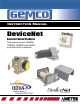
Series 956 INSTRUCTION MANUAL DeviceNet Resolver Based Products This manual covers 1986DN, 1980DN, 1990DN and 925DN units with built in resolvers.
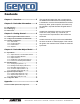
Contents Chapter 1: Overview ............................... 3 Chapter 2: DeviceNet Information ......... 4 2.1 LED Operation ...............................................................4 2.2 I/O Messaging ................................................................4 2.3 Data Format ...................................................................4 Chapter 3: Getting Started ..................... 5 3.1 Establishing DeviceNet Communications ..................5 3.
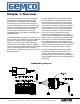
Chapter 1: Overview The DeviceNet Resolver combines the reliability and resolution of continuous resolver position sensing with the added flexibility of DeviceNet communications. The resolver technology is the same as other GEMCO resolvers which have been proven in rugged applications like stamping press automation. The rugged housing construction is ideal for harsh industrial environments. All embedded electronics are SMT constructed for the ultimate reliability.
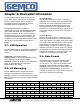
Chapter 2: DeviceNet Information The DeviceNet Resolver operates as a “Group 2 only slave” device. It operates as an input only device on the DeviceNet network. All device configurations are accomplished by using any DeviceNet software configuration tool. Bit Strobe Message The DeviceNet Resolver is capable of communicating at all three DeviceNet baud rates, 125K, 250K, and 500K. The node address can be set to any address, 0 - 63.
Chapter 3: Getting Started 3.1: Establishing DeviceNet Communications NOTE: This manual assumes that the network is configured in accordance with the DeviceNet wiring specification. 1. Remove the DeviceNet Resolver from the box and connect your DeviceNet cable to the 5-pin mini connector on the back of the resolver according to the DeviceNet wiring specifications. 2. Make sure that there is power on the DeviceNet network when you connect the DeviceNet Resolver to the network. 3.
3.3.3: Position Offset The indicated position of the resolver can be changed to synchronize or “zero” the resolver to the machine it is attached to. The resolver position can be changed by moving the resolver at the desired position and writing the desired indicated position to attribute 1 of the Position Object. All setpoints will be based on this offset position. A valid position value can range between, and include, zero and the scale factor. (i.e. 0 < position < scale factor). 6 3.3.
Chapter 4: DeviceNet Object Model 4.1: Object Model 4.1.1: Objects Present in the DeviceNet Resolver 4.1.
4.1.
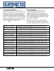
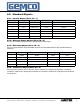
4.2: Standard Objects 4.2.1: Identity Object (Class ID = 1) Attribute ID Access Rule Name Data Type Value 1 Get Vendor UNIT 0x009C 2 Get Product Type UINT 0x0000 3 Get Product Cod UINT 0x07C2 4 Get Revision STRUCT 01.00 5 Get Status WORD 0x0000 6 Get Serial # UDINT 0x00000001 7 Get Product Name STRUCT 15, “1986DN Resolver” 4.2.2: Message Router Object (Class ID = 2) There is no externally visible interface to the Message Router Object. 4.2.
Explicit Message Connection Object (Instance #1) Attribute ID Access Rule Name Data Type Value 1 Get State USINT 0x03 2 Get instance_type USINT 0x00 3 Get Xport Class trigger USINT 0x83 4 Get Produced connection ID UINT 0x5FB for MAC ID 63 5 Get Consumed connection ID UINT 0x5FC for MAC ID 63 6 Get initial comm characteristics USINT 0x21 7 Get produced connection size UINT 0x0025 8 Get consumed connection size UINT 0x0025 9 Get/Set expected packet rate UINT A
Bit Strobe I/O Message Connection Object (Instance #3) Attribute ID Access Rule Name Data Type Value 1 Get State USINT 0x03 2 Get instance_type USINT 0x01 3 Get Xport Class trigger USINT 0x82 4 Get Produced connection ID UINT 0x3BF for MAC ID 63 5 Get consumed connection ID UINT 0x408 for MAC ID 1 6 Get initial comm characteristics USINT 0x02 7 Get produced connection size UINT 0x0005 8 Get consumed connection size UINT 0x0008 9 Get/Set expected packet rate UI
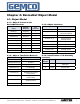
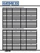
Parameter Instance #1 (Position) Attribute ID Access Rule Name Data Type Value 1 Get Parameter Value UINT Current Position 2 Get Link Path Size USINT 0x06 3 Get Link Path ARRAY “0x20 0x64 0x24 0x01 0x30 0x01” 4 Get Descriptor WORD 0x0030 5 Get Data Type USINT 0x02 6 Get Data Size USINT 0x02 Parameter Instance #2 (Scale Factor) Attribute ID Access Rule Name Data Type Value 1 Get/Set Parameter Value UINT Current Scale Factor 2 Get Link Path Size USINT 0x06 3
Parameter Instance #5 (Setpoint 1 on position) Attribute ID Access Rule Name Data Type Value 1 Get/Set Parameter Value USINT Setpoint 1 on position 2 Get Link Path Size USINT 0x06 3 Get Link Path ARRAY “0x20 0x65 0x24 0x01 0x30 0x02” 4 Get Descriptor WORD 0x0000 5 Get Data Type USINT 0x02 6 Get Data Size USINT 0x02 Parameter Instance #6 (Setpoint 1 off position) Attribute ID Access Rule Name Data Type Value 1 Get/Set Parameter Value USINT Setpoint 1 off position 2
Parameter Instance #9 (Setpoint 3 on position) Attribute ID Access Rule Name Data Type Value 1 Get/Set Parameter Value USINT Setpoint 3 on position 2 Get Link Path Size USINT 0x06 3 Get Link Path ARRAY “0x20 0x65 0x24 0x03 0x30 0x02” 4 Get Descriptor WORD 0x0000 5 Get Data Type USINT 0x02 6 Get Data Size USINT 0x02 Parameter Instance #10 (Setpoint 3 off position) Attribute ID Access Rule Name Data Type Value 1 Get/Set Parameter Value USINT Setpoint 3 off position
Parameter Instance #13 (Setpoint 5 on position) Attribute ID Access Rule Name Data Type Value 1 Get/Set Parameter Value USINT Setpoint 5 on position 2 Get Link Path Size USINT 0x06 3 Get Link Path ARRAY “0x20 0x65 0x24 0x05 0x30 0x02” 4 Get Descriptor WORD 0x0000 5 Get Data Type USINT 0x02 6 Get Data Size USINT 0x02 Parameter Instance #14 (Setpoint 5 off position) Attribute ID Access Rule Name Data Type Value 1 Get/Set Parameter Value USINT Setpoint 5 off position
Parameter Instance #17 (Setpoint 7 on position) Attribute ID Access Rule Name Data Type Value 1 Get/Set Parameter Value USINT Setpoint 7 on position 2 Get Link Path Size USINT 0x06 3 Get Link Path ARRAY “0x20 0x65 0x24 0x07 0x30 0x02” 4 Get Descriptor WORD 0x0000 5 Get Data Type USINT 0x02 6 Get Data Size USINT 0x02 Parameter Instance #18 (Setpoint 7 off position) Attribute ID Access Rule Name Data Type Value 1 Get/Set Parameter Value USINT Setpoint 7 off position
4.3: Application Specific Objects 4.3.1: Position Object (Class ID = 100) There is a single instance of the position object for the DeviceNet Resolver. No class attributes are supported. All the instances are gettable and settable.
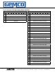
4.4: Configuration Notes Network Baud Rate DeviceNet Resolver Node Address Scale Factor Counting Direction Setpoint 1 “On” Setpoint 1 “Off” Setpoint 2 “On” Setpoint 2 “Off” Setpoint 3 “On” Setpoint 3 “Off” Setpoint 4 “On” Setpoint 4 “Off” Setpoint 5 “On” Setpoint 5 “Off” Setpoint 6 “On” Setpoint 6 “Off” Setpoint 7 “On” Setpoint 7 “Off” Setpoint 8 “On” Setpoint 8 “Off” 18 1080 N. Crooks Road • Clawson, MI 48017 • 800.635.0289 • 248.435.0700 • Fax 248.435.8120 • www.AMETEKAPT.
Appendix Specifications Resolver Resolution 12 bit resolution (4096 counts) RPM 1024 max. DeviceNet Conformance Device Type This product has been tested by ODVA’s authorized Independent Test Lab and found to comply with ODVA Conformance Test Software Version A-12.
Other Products Copyright 2007 by AMETEK Automation & Process Technologies. All Rights Reserved. Made in the USA. 1080 N. Crooks Road, Clawson, MI 48017-1097 Phone 248-435-0700 Toll Free 800-635-0289 Fax 248-435-8120 www.ametekapt.com DNRES.M3R 3/07.