
Instruction Manual

2
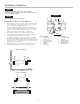
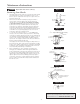
Outdoor Installation
NOTICE
The flange gasket bolts for the gate valves should be
retightened during installation as the bolts may have loosened
due to storage and shipping.
NOTICE
Assembly body should not be painted.
Please Read Prior to Installation:
1. Before installing any Ames assembly, Flush the Line thoroughly
to remove all debris, chips and other foreign objects. Failure to
do so may make the assembly inoperable.
2. The Ames 4000SS and 5000SS Reduced Pressure Zone As-
semblies are approved by ASSE (American Society of Sanitation
Engineers) to be installed in horizontal positions. Local water
authorities must approve all installation configurations.
3. Allow sufficient clearance around the installed assembly to
conduct testing, servicing, and inspection. Allow a minimum of 12"
from the flood level to the bottom of the assembly.
4. The 4000SS and 5000SS are not recommended for pit installa-
tions. Where necessary, an Air Gap drain may be connected to
the relief valve to minimize flooding of the surrounding area. Flood-
ing may cause a cross-connection. Be sure to contact local code
authorities for proper installations.
5. If installing on fire protection system, be sure to purge air from fire
system. Fill system slowly with all inspectors test valves open.
Installation Guidelines
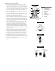
Item # Description
1. #1 Cam-Check
2. #2 Cam-Check
3. #1 Cam-Check O-ring
4. #2 Cam-Check O-ring
5. Cover Plate
6. Ball Valve
7. Groove Coupler
Item # Description
8. Groove Coupler Gasket
9. Relief Valve
(Complete assembly)
10. Relief Valve Hose
11. Relief Valve Body O-ring
12. Ball Valve (Cover)
Figure 1
Flow
1
2
3
4
5
6
7
8
9
11
10
12
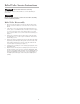
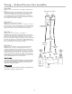
Indoor Installation