
User Manual

3
Installation Instructions
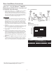
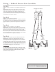
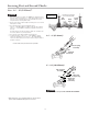
A. Series 5000CIV should be installed in a horizontal and upright
position. This positions the relief valve below the first check valve,
enabling the zone to drain through the relief valve outlet. The
shutoff valve with the test cock is to be mounted on the inlet side
of the backflow preventer. The test cock is on the inlet side of the
shutoff valve.
B. The Series 5000CIV should always be installed in an accessible
location to facilitate testing and servicing. Check the state and
local codes to insure that the backflow preventer is installed in
compliance, such as the proper height above the ground.
C. Water discharge from the relief valve should be vented in ac-
cordance with code requirements. The relief valve should never
be solidly piped into a drainage ditch, sewer or sump. The
discharge should be funneled through a air gap fitting piped to a
floor drain.
CAUTION
!
Do not install a strainer ahead of the backflow preventer on seldom-
used, emergency water lines (i.e. fire sprinkler lines). The strainer
mesh could potentially become clogged with debris present in the
water and cause water blockage during an emer gen cy.
D. Ames recommends a strainer be installed ahead of Series 5000
assemblies to protect the discs from unnecessary fouling.
E. Backflow preventers should never be placed in pits unless abso-
lutely necessary and then only when and as approved by local
codes. Consult your local or state plumbing or health inspector.
Ames recommends installation indoors or above ground in an
insulated enclosure.
Consult local authorities regarding acceptance of vertical installations.
Start Up
F. The downstream shutoff should be closed. Open upstream
slowly, fill the valve and bleed the air through Test cock 2, 3 and
4. When valve is filled, open the downstream shutoff slowly and
fill the water supply system. This is necessary to avoid water
hammer or shock damage.
G. The installation of an air gap with the drain line terminating above
a floor drain will handle any normal discharge or nuisance spit-
ting through the relief valve. However, floor drain size may need
to be designed to prevent water damage caused by a cata-
strophic failure condition. Do not reduce the size of the drain line
from the air gap fitting.
H. Two or more smaller size valves can be piped in parallel (when
approved) to serve a larger supply pipe main. This type of instal-
lation is employed where increased capacity is needed beyond
that provided by a single valve and permits testing or servicing of
an individual valve without shutting down the complete line.
The number of assemblies used in parallel should be determined by
the engineer’s judgement based on the operating conditions of a
specific installation.
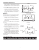
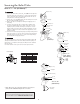
Indoors
Above Ground
Parallel
Now available, WattsBox Insulated Enclosures, for more information,
send for ES-WB.
Min. 12" (300mm)
Series 5000
2
1
⁄2" – 10"
(65-250mm)**
Strainer
Air Gap
Series 5000
2
1
⁄2" - 10"
(65-250mm)**
Meter Strainer
Main
Air
Gap
12" (300mm)
support
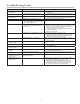
TABLE ONE - CAPACITY REQUIRED FOR SYSTEM
50 GPM 100 GPM 150 GPM 200 GPM 250 GPM 350 GPM 450 GPM 640 GPM 1000 GPM 2000 GPM 3000 GPM 5000 GPM
Two
3
⁄4" Two 1" Two 1
1
⁄4" Two 1
1
⁄2" Two 1
1
⁄2" Two 2" Two 2
1
⁄2" Two 3" Two 4" Two 6" Two 8" Two 10"
Devices Devices Devices Devices Devices Devices Devices Devices Devices Devices Devices Devices
Table shows total capacity provided with dual valve installations of various sizes.
Figure 2
Figure 1