5594500COM 6 Drawer Dresser B345594500COM0 Date of Purchase ___ / ___ / ___ Lot Number: Do Not Return This Product! Contact our customer service team for help first. Call: 1-800-489-3351 (toll free) Monday-Friday 9am - 5pm CST Visit: www.ameriwoodhome.com THIS INSTRUCTION BOOKLET CONTAINS IMPORTANT SAFETY INFORMATION. PLEASE READ AND KEEP FOR FUTURE REFERENCE. Secure Your Furniture Keep your home and family safe with the wall anchor kit that is included with the product.
Contact Us! Do NOT return this product! Contact our friendly customer service team first for help. Assembly Tips Call us! 1-800-489-3351 Monday-Friday 9am - 5pm CST Visit ameriwoodhome.com to view the limited warranty valid in the U.S. and Canada. You Tube Helpful Hints PEOPLE NEEDED FOR ASSEMBLY: 1-2 ESTIMATED ASSEMBLY TIME: 2-3 HOURS - Open your item in the area you plan to keep it to avoid excessive heavy lifting. - Identify, sort and count the parts before attempting assembly.
k Quic bly em Ass Tip Before You Start P P P P P Read through each step carefully and follow the proper order Separate and count all your parts and hardware Give yourself enough room for the assembly process Have the following tools: Flat Head Screwdriver, #2 Phillips Head Screwdriver and Hammer Caution: If using a power drill or power screwdriver for screwing, please be aware to slow down and stop when screw is tight. Failure to do so may result in stripping the screw.
Board Identification Not actual size B A D C Left Panel 35594340010 Top 35594340030 Right Panel 35594340020 Bottom 35594340040 E G F H Left Base Rail 35594340080 ameriwoodhome.
Board Identification Not actual size N M L Partition 35594340130 Drawer Brace (6) 35538000121 Drawer Front (6) 35594333140 O P Q Side Rail (4) 35594340160 Drawer Bottom (6) 35594331150 Apron (2) 35594340170 This piece is paperboard construction. It is not made from wood, but is required for the assembly of your unit. S R Upper Side Molding (2) 35594340180 T Upper Front Molding 35594340190 ameriwoodhome.
Board Identification Not actual size This piece is paperboard construction. It is not made from wood, but is required for the assembly of your unit. P R K C S M T J B Q E R P E P E J A K D E I Q P F G H ameriwoodhome.
Board Identification Not actual size DWR SIDE DWR BACK O N DWR SIDE L ameriwoodhome.
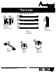
Part List Actual Size 3 1 2 (x28) #A22620 (x28) #A22610 cam lock 7 (x12) #A17250 bolt 4 cam bolt 9 (x9) #A21660 wood dowel (x92) #A12120 #6 x 7/16" screw #8 x 7/16" screw 10 (x20) #A12930 #8 x 1-1/8" screw 13 (x60) #A11080 connector bolt connector 8 12 (x4) #A22910 (x4) #A22920 6 5 11 (x11) #A13020 #8 x 1-1/2" screw 14 (x22) #A53600 angle bracket 15 16 (x6) #A23030 confirmat screw (x4) #A21550 5x50 wood dowel ameriwoodhome.
Part List Not actual size 17a 18a 17c Left Cabinet Member 17d 18b 19 Right Cabinet Member 17b (x1) #A84050 safety bracket kit 18c Left Drawer Member 18d (x12) #A54520 Right Drawer Member (x6) #A56750 drawer bracket drawer slide 22 20 (x6) #A50875 handle ameriwoodhome.
STEP 1 Using screw (9), attach the front vertical molding (J) and rear vertical molding (K) to the left panel (A). 9 Please be sure to screw into the surface of the front vertical molding with the pilot holes. Do not fully tighten the screws until next step is completed. (x6) #A12930 Pilot hole in front vertical molding. 9 J 9 A 9 9 K 9 9 ameriwoodhome.
STEP 2 Using screw (9), attach the side moldings (P) to the left panel (A). 9 Now tighten the screws that were left loose in the previous step. (x4) #A12930 P 9 J A P 9 9 K ameriwoodhome.
STEP 3 1 marked with a "L" 2 (x2) #A22620 18a 5 (x2) #A22610 (x3) #A56750 (x9) #A11080 Quick Assembly Tip Proper orientation of CAM LOCK 18a 2 18a 1 18a A J 5 1 2 ameriwoodhome.
STEP 4 9 Using screw (9), attach the front vertical molding (J) and rear vertical molding (K) to the right panel (B). Please be sure to screw into the surface of the front vertical molding with the pilot holes. Do not fully tighten the screws until next step is completed. Pilot hole in front (x6) #A12930 vertical molding. 9 J 9 9 B 9 K 9 9 ameriwoodhome.
STEP 5 Using screw (9), attach the side moldings (P) to the right panel (B). 9 Now tighten the screws that were left loose in the previous step. (x4) #A12930 P 9 J 9 B 9 P 9 ameriwoodhome.
STEP 6 1 marked with a "R" 2 (x2) #A22620 18b 5 (x2) #A22610 (x3) #A56750 (x9) #A11080 Quick Assembly Tip Proper orientation of CAM LOCK 18b 2 18b 18b 5 2 1 18b ameriwoodhome.
STEP 7 3 1 2 (x4) #A22620 (x4) #A22610 (x4) #A22920 2 1 H 3 3 2 1 Postition the connector as shown before inserting. You will need to use a hammer to fully insert. 3 Quick I 3 Assembly Tip Proper orientation of CAM LOCK ameriwoodhome.
STEP 8 6 1 11 (x5) #A12120 (x4) #A22620 (x5) #A53600 1 6 11 6 1 11 6 11 6 11 1 G 11 6 Quick Assembly Tip 1 Proper orientation of CAM LOCK ameriwoodhome.
STEP 9 2 6 (x4) #A22610 (x5) #A12120 11 (x5) #A53600 2 6 6 2 11 11 6 11 6 11 2 11 F 6 2 ameriwoodhome.
STEP 10 22 21 4 (x4) #A22910 (x2) #A43490 (x1) #A43105 4 4 22 21 21 4 D 4 ameriwoodhome.
STEP 11 Press the right base rail (I) onto the bottom (D) so the connectors (3) engage the connector bolts (4). Turn the screw in the connector clockwise to lock in place. 3 Turn screw clockwise to lock in place. I D finished edge ameriwoodhome.
STEP 12 UNLOCK LOCK Attach the rear base rail (G) to the right base rail (I) as shown. I G D ameriwoodhome.
STEP 13 6 LOCK UNLOCK (x5) #A12120 Press the left base rail (H) onto the rear base rail (G) as shown making sure the connectors (3) in the left base rail (H) engage the connector bolt (4) in the bottom (D). Securely fasten the cam locks (1) and connectors (3). Attach the rear base rail (G) to the bottom (D) using 5 screws (6). 3 6 Turn screw clockwise to lock in place. H D G ameriwoodhome.
STEP 14 6 (x5) #A12120 UNLOCK LOCK Secure the front base rail (F) to the left and right base rails (H&I) as shown then secure to the bottom (D) with five screws (6). 6 I F H ameriwoodhome.
STEP 15 6 11 (x12) #A12120 (x6) #A53600 Do not fully tighten the screws (6) in this step. 6 raw surface 6 Q 11 Q D ameriwoodhome.
STEP 16 8 2 5 (x2) #A22610 marked with a "R" 18b (x3) #A56770 (x1) #A21660 (x9) #A11080 Attach slides (18b) and cam bolts (2) to left side of Partition (M). 5 18b 18b 2 2 18b M 5 18b ameriwoodhome.
STEP 17 marked with a "L" 2 1 (x2) #A22620 18a 5 (x2) #A22610 (x3) #A56770 (x9) #A11080 Turn the Partition (M) over and attch slides (18a) and cam locks (2) to right side. 1 18a 18a 18a 2 M 1 Quick 5 Assembly Tip Proper orientation of CAM LOCK 18a ameriwoodhome.
STEP 18 With the help of another person, attach the partition (M) to the bottom (D) using two screws (12). If needed, adjust the apron (Q) so that the holes in the partition (M) lined up with the holes in the bottom (D). 12 (x2) #A23030 Q M F 12 D 12 Q M end view ameriwoodhome.
STEP 19 8 1 (x8) #A22620 (x8) #A21660 1 Quick Assembly Tip 8 Proper orientation of CAM LOCK 1 E x4 8 ameriwoodhome.
STEP 20 finished edge LOCK UNLOCK E E M E E ameriwoodhome.
STEP 21 12 (x4) #A23030 Place the left panel assembly and the right panel assembly as shown and tighten the four cam locks (1). A E E Attach the left panel (A) and right panel (B) to the bottom (D) using 4 screws (12). Adjust the apron (Q) if needed to fix properly. Now tighten the screws (6) left loose from step 15. A LOCK UNLOCK E E 12 E E B 12 12 ameriwoodhome.
STEP 22 10 (x11) #A13020 13 Insert four long wood dowels (13) into the larger holes in the top (C). Press the two upper side moldings (R) onto the wood dowels (13) and press until seated onto the top (C). Fasten to the top (C) with screws (10) as shown. Position the upper front molding (S) as shown and attach with screws (10) as shown. (x4) #A21550 Be sure to use the holes shown. flat edge R 10 13 flat edge C S R finished edge 13 ameriwoodhome.
STEP 23 2 11 6 17a 17b (x6) #A22610 (x12) #A12120 (x1) #A84050 (x6) #A53600 Do not fully tighten the screws (6) in this step. 6 2 11 R 6 Q 2 C 2 2 S 17b 2 2 ameriwoodhome.com Do not fully tighten this screw in this step.
STEP 24 If needed, adjust the apron (Q) so that it fits properly. Now tighten the screws (6) that were left loose from step 23. LOCK UNLOCK A C Q B ameriwoodhome.
STEP 25 16 IMPORTANT! THE BACK PANEL IS A STRUCTURAL PART OF THIS UNIT AND MUST BE INSTALLED PROPERLY. (x36) #A21110 With the help of another person, carefully turn your unit over on its front side as shown. Position the back panel as shown making sure bottom edge is flush with the edge of the bottom and side edges are aligned squarely with the left and right panels. Nail straight into the back edge of the left and right panels, top and bottom as shown.
STEP 26 17c 17d For Masonry, Concrete, or other wall materials: Consult your local hardware store for appropriate anchors to securely attach the safety bracket. IMPORTANT: THIS UNIT MUST BE SECURE TO THE WALL TO HELP PREVENT TIPOVER. FOLLOW THESE INSTRUCTIONS TO INSTALL THE ANTI-TIPPING SAFETY BRACKET PROVIDED WITH THIS PRODUCT. WARNING hole Serious or fatal crushing injuries can occur from furniture tipover.
STEP 27 2 6 (x6) #A22610 19 (x12) #A54520 (x24) #A12120 6 2 19 6 6 N 6 x6 19 ameriwoodhome.
STEP 28 1 (x6) #A22620 L x6 15 6 (x6) #A21520 (x24) #A12120 15 Quick Assembly Tip Proper orientation of CAM LOCK 1 DWR SIDE 6 L DWR SIDE 6 N x6 6 6 ameriwoodhome.
STEP 29 raw surface O DWR SIDE L N DWR SIDE x6 ameriwoodhome.
STEP 30 14 (x36) #A21970 14 14 14 DWR BACK DWR SIDE 14 O 14 DWR SIDE x6 ameriwoodhome.
STEP 31 5 18c 7 18d (x24) #A11080 (x12) #A17400 marked with a "L" marked with a "R" (x6) #A56750 18d 20 5 (x6) #A50875 5 DWR BACK DWR SIDE 18c 5 7 DWR SIDE 7 5 x6 20 Attach handle after installing the drawer slides. ameriwoodhome.
STEP 32 cabinet member roller roller drawer runner Note: The drawer bracket holes are slotted. Drawer fronts can be adjusted by loosening screws, making needed adjustments and retightening screws. ameriwoodhome.
Maximum Loads This unit has been designed to support the maximum loads shown. Exceeding these load limits could cause sagging, instability, product collapse, and/or serious injury. 35 lbs 15.9 kg Per Drawer 75 lbs 34 kg Warning: Risk of injury to persons - do not place a television on this furniture. This furniture is not approved for use with a television. Certificate of Conformity 1. This certificate applies to the Dorel Home Furnishings, Inc. product identified by this instruction manual. 2.
Register your product to receive the following: * New trend details - sneak peek on what's new * Surveys - have a voice within our community * Exclusive deals and discount codes * Quick and easy replacement part service To register your product, visit ameriwoodhome.
Español Cubierta Delantera Este libro de instrucciones contiene información IMPORTANTE de seguridad. Por favor lea y manténgalo para referencia en el futuro. No Regrese este producto! Comuniquese con nuestro amistoso equipo de servicio al cliente para obtener ayuda. Llamenos al: 1-800-489-3351 (Gratis) Lunes - Viernes 9am - 5pm CST Visitar: www.ameriwoodhome.com PRECAUCION Este mueble puede volcarse y causar graves heridas y/o muerte. Anclar el mueble a un poste de madera en la pared (si esto se requiere).
Español Página 10 Utilizando un tornillo (9), fije la moldura vertical frontal (J) y la moldura vertical trasera (K) al panel izquierdo (A). Por favor, asegúrese de atornillar en la superficie de la moldura vertical frontal utilizando los orificios guía. No apriete totalmente los tornillos hasta completar el siguiente paso. Coloque el orificio guía en la moldura vertical frontal. Página 11 Utilizando un tornillo (9), fije las molduras laterales (P) al panel izquierdo (A).
Español Página 23 Fije el riel base frontal (F) a los rieles base izquierdo y derecho (H&I) tal y como se muestra y luego fíjelo a la parte inferior (D) con cinco tornillos (6). Página 24 No apriete totalmente los tornillos (6) en este paso. Página 27 Con la ayuda de otra persona, fije la división (M) a la parte inferior (D) utilizando dos tornillos (12). Si es necesario, ajuste la plataforma (Q) de modo que los agujeros de la división (M) se alineen con los agujeros de la parte inferior (D).
Español Página 34 IMPORTANTE: EL PANEL TRASERO ES UNA PARTE ESTRUCTURAL DE ESTA UNIDAD Y DEBE INSTALARSE DE FORMA APROPIADA. Con ayuda de otra persona, voltee cuidadosamente su unidad para que quede de frente tal y como se muestra. Coloque el panel trasero según se muestra asegurándose de que la orilla inferior quede nivelada con la orilla de la parte inferior y las orillas laterales estén perfectamente alineadas con los paneles izquierdo y derecho.
Español OPCIÓN 2: Sujeción a un panel de tablarroca Ubique su unidad contra una pared donde desea colocarla y marque la pared a través del soporte de seguridad y luego haga a un lado su unidad. Haga una perforación de 3/16" (5mm) de diámetro en la tablarroca. Dé unos pequeños golpes al anclaje de la pared para alinearlo con el agujero. Mueva su unidad al lugar y fije el soporte de pared al anclaje de pared con el tornillo. Apriete el tornillo que no quedó totalmente apretado en el paso 23.
Français Couverture Avant CE LIVRET D'INSTRUCTION CONTIENT DES INFORMATIONS IMPORTANTES SUR LA SÉCURITÉ. VEUILLEZ LIRE ET GARDER POUR UNE RÉFÉRENCE FUTURE Ne retournez pas ce produit! Contactez notre équipe de service à la clientèle amicale d'abord pour obtenir de l'aide. Appelez-nous: 1-800-489-3351 (sans frais) du Lundi au Vendredi de 9h à 17h Heure Centrale Visitez: www.ameriwoodhome.com ATTENTION Le meuble peut basculer et causer des blessures graves ou la mort.
Français Page 10 En utilisant la vis (9), fixez la moulure verticale avant (J) et la moulure verticale arrière (K) au panneau gauche (A). Assurez de viser dans la surface de la moulure verticale avant à l'aide des trous de guidage. Ne serrez pas entièrement les vis avant la fin de la prochaine étape. Trou de guidage dans la moulure verticale avant. Page 11 En utilisant la vis (9), fixez les moulures latérales (P) au panneau gauche (A).
Français Page 23 Fixez bien la traverse avant (F) aux traverses gauche et droite (H et I) comme montré, puis fixez-la bien au fond (D) avec cinq vis (6). Page 24 Ne serrez pas entièrement les vis (6) lors de cette étape. Page 27 Avec l'aide d'une autre personne, fixez la cloison (M) au fond (D) en utilisant deux vis (12). Si besoin, ajustez le tablier (Q) afin que les trous dans la cloison (M) soient alignés à ceux du fond (D).
Français Page 34 IMPORTANT : LE PANNEAU ARRIÈRE EST UN ÉLÉMENT STRUCTUREL DE CETTE UNITÉ ET DOIT ÊTRE INSTALLÉ CORRECTEMENT. Avec l'aide d'une autre personne, retournez prudemment votre meuble sur sa face avant comme montré. Positionnez le panneau arrière comme montré en vous assurant que le bord inférieur soit aligné avec le bord du fond et que les bords des côtés soient bien alignés avec les panneaux gauche et droit.
Français OPTION 2 : fixer à une cloison sèche Placez votre unité à l'endroit de votre choix contre un mur et faites une marque sur ce dernier à travers l'entretoise de sécurité, puis déplacez l'unité plus loin. Percez un trou de 5 mm de diamètre (3/16'') dans la plaque de plâtre. Enfoncez l'ancrage mural dans le trou jusqu'à ce qu'il soit aligné. Mettez votre unité en place et fixez le support mural à l'ancrage mural avec la vis. Serrez bien la vis qui ne l'étaient pas entièrement dans l'étape 23.