9866012COM 3 In One Desk B349866012COM0 Date of Purchase ___ / ___ / ___ Lot Number: Do Not Return This Product! Contact our customer service team for help first. Call: 1-800-489-3351 (toll free) Monday-Friday 9am - 5pm CST Visit: www.ameriwoodhome.com THIS INSTRUCTION BOOKLET CONTAINS IMPORTANT SAFETY INFORMATION. PLEASE READ AND KEEP FOR FUTURE REFERENCE. Secure Your Furniture Keep your home and family safe with the wall anchor kit that is included with the product.
Contact Us! Do NOT return this product! Contact our friendly customer service team first for help. Assembly Tips Call us! 1-800-489-3351 Monday-Friday 9am - 5pm CST Visit ameriwoodhome.com to view the limited warranty valid in the U.S. and Canada. You Tube Helpful Hints PEOPLE NEEDED FOR ASSEMBLY: 1-2 ESTIMATED ASSEMBLY TIME: 2-3 HOURS - Open your item in the area you plan to keep it to avoid excessive heavy lifting. - Identify, sort and count the parts before attempting assembly.
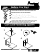
k Quic bly em Ass Tip Before You Start P P P P P Read through each step carefully and follow the proper order Separate and count all your parts and hardware Give yourself enough room for the assembly process Have the following tools: Flat Head Screwdriver, #2 Phillips Head Screwdriver and Hammer Caution: If using a power drill or power screwdriver for screwing, please be aware to slow down and stop when screw is tight. Failure to do so may result in stripping the screw.
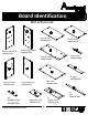
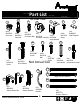
Board Identification Not actual size B A C Dresser Top 39866012030 Dresser Left Panel 39866012010 E Dresser Shelf 39866012050 F D Dresser Right Panel 39866012020 Dresser Bottom 39866012040 Dresser Leg 39866012060 G K J I Stringer 39866000070 Desk Left Panel 39866012100 Desk Top 39866012090 Desk Right Panel 39866012110 H L x3 Drawer Brace 35538000121 ameriwoodhome.
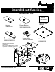
Board Identification Not actual size WARNING O P AVERTISSMENT Warning Label B64339 x3 Drawer Bottom 39991340062410D Modesty 39866012140 Q DWR SIDE DWR BACK x6 Drawer Side 39991167346200C x3 Drawer Back 39991167061450B Back Panel K986601200 O These pieces are paperboard construction. They are not made from wood, but are required for the assembly of your unit. I C Q K E M G J B DWR SIDE DWR BACK A D DWR SIDE H F ameriwoodhome.
Part List 2 1 (x24) #A22620 Cam Lock 3 Actual Size (x2) #A22910 (x24) #A22610 5 4 6 (x44) #A12120 (x2) Connector Bolt #A22920 Cam Bolt (x10) Connector Housing #A53600 7 Screw (x4) #A80250 Shelf Support Angle Bracket 11 10 13 18 9 8 (x30) #A11080 (x40) #A21110 Screw (x7) #A13410 Screw (x18) #A21970 Drive Fastner Nail (x6) #A12700 Screw Not Actual Size 14c 14d (x10) #A21660 wood dowel (x3) #A21520 compression dowel 17a 16 14a 12 Left Cabinet Member 17b 15 Right Cab
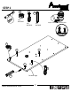
STEP 1 2 1 Quick 13 Assembly Tip (x2) #A22620 (x3) #A22610 Proper orientation of CAM LOCK (x1) #A21660 1 2 2 A 1 2 13 ameriwoodhome.
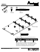
STEP 2 10 17a Marked with a "L" Left Cabinet Member (x9) #A11080 (x3) #A56770 A finished edge 10 marked with an 'L' Screw Position / Posción del tornillo / Position de la vis 17a Note that the slide sets come bundled together. Each bunndle will make one drawer. You will need to open all 3 bundles to complete this step. See page 6 of these instructions for clarification of what is in a bundle. ameriwoodhome.
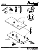
STEP 3 2 1 Quick 13 Assembly Tip (x2) #A22620 (x5) #A22610 Proper orientation of CAM LOCK (x1) #A21660 finished edge 2 B 2 B 2 1 2 finished edge 1 ameriwoodhome.
STEP 4 10 17b (x9) #A11080 Marked with a "R" Right Cabinet Member (x3) #A56770 B finished edge 10 marked with an 'R' Screw Position / Posción del tornillo / Position de la vis 17b Note that the slide sets come bundled together. Each bunndle will make one drawer. You will need to open all 3 bundles to complete this step. See page 6 of these instructions for clarification of what is in a bundle. ameriwoodhome.
STEP 5 2 14b 14a (x4) #A22610 (x1) #A84050 Do not fully tighten this screw. 2 14b 14a C 2 2 finished edge ameriwoodhome.
STEP 6 1 3 13 8 Quick Assembly Tip (x2) #A22620 (x2) #A22910 Proper orientation of CAM LOCK (x1) #A21660 (x2) #A13410 13 A D 8 3 8 ameriwoodhome.
STEP 7 13 1 Quick Assembly Tip (x6) #A22620 (x4) #A21660 Proper orientation of CAM LOCK 1 1 13 1 E 1 1 13 13 1 G 13 ameriwoodhome.
STEP 8 UNLOCK A E G D ameriwoodhome.
STEP 9 8 (x2) #A13410 UNLOCK LOCK Press the right panel (B) against the Stringer (G) and the Dresser Shelf (E) so the cam bolts (2) insert into the end hole of the Stringer (G) and the Dresser Shelf (E). Turn the cam locks (1) clockwise to lock in place. Attach the bottom (D) to the right panel (B) with two screws (8) as shown. B E G 8 D A 8 ameriwoodhome.
STEP 10 UNLOCK finished edge C A E G D ameriwoodhome.
STEP 11 11 WITH THE HELP OF ANOTHER PERSON, TURN UNIT OVER (x36) #A21110 IMPORTANT! THE BACK PANEL IS A STRUCTURAL PART OF THIS UNIT AND MUST BE INSTALLED PROPERLY. Position the back panel as shown. Flush the bottom edge of the back panel with the bottom edge of the bottom (D). Align squarely and nail (6) straight into back edges as shown. 11 Notch in back panel positioned here. Assure that the unit is square. Distance from corner to corner are equal.
STEP 12 4 (x2) #A22920 You will need to tap the connector (4) with a hammer to fully insert. Be sure the connector is positioned as shown before pushing into hole. 4 4 F ameriwoodhome.
STEP 13 UNLOCK LOCK Raw edge F D ameriwoodhome.
STEP 14 5 (x8) #A53600 6 WITH THE HELP OF ANOTHER PERSON, TURN UNIT ON TOP SIDE (C) (x16) #A12120 6 6 H H ameriwoodhome.
STEP 15 2 1 13 Quick Assembly Tip (x2) #A22620 (x3) #A22610 (x1) #A21660 Proper orientation of CAM LOCK 2 2 K 1 13 1 ameriwoodhome.
STEP 16 2 1 13 Quick Assembly Tip (x2) #A22620 (x1) #A21660 (x4) #A22610 Proper orientation of CAM LOCK 2 2 I 1 2 13 1 ameriwoodhome.
STEP 17 2 1 Quick 13 (x2) #A22620 (x2) #A22610 Assembly Tip (x1) #A21660 Proper orientation of CAM LOCK 2 2 J 1 13 1 ameriwoodhome.
STEP 18 Quick 1 Assembly Tip (x3) #A22620 Proper orientation of CAM LOCK 1 O 1 1 ameriwoodhome.
STEP 19 UNLOCK O K ameriwoodhome.
STEP 20 8 (x3) #A13410 K O J 8 8 ameriwoodhome.
STEP 21 UN LOCK I K O J ameriwoodhome.
STEP 22 UNLOCK ameriwoodhome.
STEP 23 5 (x2) #A53600 6 (x4) #A12120 6 6 6 ameriwoodhome.
STEP 24 2 6 (x3) #A22610 (x12) #A12120 15 (x6) #A54520 Note: For the next several steps you will be assembling the drawer. Your model has three drawers. You will repeat each step three times until all three drawers are assembled. 6 16 6 16 N 2 x3 ameriwoodhome.
STEP 25 6 (x12) #A12120 Be sure the groove in the drawer sides is centered with the groove in the drawer front. If needed, loosen screws (4) in the drawer front, make needed adjustment and re-tighten screws. 6 DWR SIDE N DWR SIDE x3 6 ameriwoodhome.
STEP 26 1 18 Quick Assembly Tip (x3) #A22620 Proper orientation of CAM LOCK (x3) #A21520 You will need to tap the compression dowel (18) with a hammer to fully insert. 1 18 L x3 ameriwoodhome.
STEP 27 UNLOCK DWR SIDE L DWR SIDE N x3 ameriwoodhome.
STEP 28 Slide the drawer bottom (P) into the groove of the drawer sides and drawer front. raw surface P DWR SIDE L DWR SIDE N x3 ameriwoodhome.
STEP 29 9 You will need to tap with a hammer to fasten. 9 9 (x18) #A21970 9 DWR SIDE DWR BACK L 9 9 DWR SIDE x3 ameriwoodhome.
STEP 30 16 10 12 17c Left Drawer Member (x12) #A11080 17d Right Drawer Member (x3) #A56770 (x6) #A12700 (x3) #A50695 Marked with a "R" 17d Attach slides before handle. 10 DWR SIDE 17c Marked with a "L" 12 10 DWR SIDE 12 16 ameriwoodhome.
STEP 31 14c 14d For Masonry, Concrete, or other wall materials: Consult your local hardware store for appropriate anchors to securely attach the safety bracket. (x1) #A84050 IMPORTANT: THIS UNIT MUST BE SECURE TO THE WALL TO HELP PREVENT TIPOVER. FOLLOW THESE INSTRUCTIONS TO INSTALL THE ANTI-TIPPING SAFETY BRACKET PROVIDED WITH THIS PRODUCT. WARNING Serious or fatal crushing injuries can hole occur from furniture tipover.
STEP 32 Note: The drawer bracket holes are slotted. Drawer fronts can be adjusted by loosening screws, making needed adjustments and retightening screws. cabinet member roller roller drawer runner drawer member cabinet member corredera de mueble corredera de cajón coulisse du tiroior coulisse du cabinet ameriwoodhome.
STEP 33 7 (x4) #A80250 Insert 4 shelf support pins then put the adjustable shelf on them as shown. M 7 ameriwoodhome.
Maximum Loads This unit has been designed to support the maximum loads shown. Exceeding these load limits could cause sagging, instability, product collapse, and/or serious injury. 25 lbs 11.3 kg (each drawer) 40 lbs 18.1 kg Warning Label 100 lbs 45.4 kg 50 lbs 22.7 kg 20 lbs 9.1 kg Apply the WARNING LABEL to the TOP (C). You should be able to read the label when the TV is removed from the unit. When the TV is in place, it should hide the label. Peel off the backing and apply the label as shown.
Register your product to receive the following: * New trend details - sneak peek on what's new * Surveys - have a voice within our community * Exclusive deals and discount codes * Quick and easy replacement part service To register your product, visit ameriwoodhome.
Español Cubierta Delantera Este libro de instrucciones contiene información IMPORTANTE de seguridad. Por favor lea y manténgalo para referencia en el futuro. No Regrese este producto! Comuniquese con nuestro amistoso equipo de servicio al cliente para obtener ayuda. Llamenos al: 1-800-489-3351 (Gratis) Lunes - Viernes 9am - 5pm CST Visitar: www.ameriwoodhome.com PRECAUCION Este mueble puede volcarse y causar graves heridas y/o muerte. Anclar el mueble a un poste de madera en la pared (si esto se requiere).
Español Página 10 Tenga en cuenta que los conjuntos de diapositivas vienen agrupados. Cada paquete hará un cajón. Usted tendrá que abrir los 3 paquetes para completar este paso. Vea la página 6 de estas instrucciones para clarificar lo que está en un paquete. Página 11 No apriete completamente este tornillo.
Español Página 35 Usted tendrá que golpear con un martillo para sujetar. Página 36 Fije las correderas antes del mango. Página 37 Para mampostería, concreto u otro tipo de paredes: Acude a tu ferretería local para obtener los anclajes adecuados para fijar de forma segura el soporte de seguridad. IMPORTANTE: ESTA UNIDAD DEBE ASEGURARSE A UNA PARED PARA EVITAR QUE SE VUELQUE. SIGUE ESTAS INSTRUCCIONES PARA INSTALAR EL SOPORTE DE SEGURIDAD ANTICAÍDA QUE SE PROPORCIONA JUNTO CON ESTE PRODUCTO.
Español Página 38 Nota: Los agujeros en el soporte del cajón están ranurados. Los frentes de los cajones se pueden ajustar aflojando los tornillos, haciendo los ajustes necesarios y apretando los tornillos. Página 39 CARGA MAXIMA Esta unidad ha sido diseñada para soportar la carga máxima anotada. El exceder estos límites puede causar inestabilidad, colapsarse y/o causar serias lesiones. ADVERTENCIA: Riesgo de lesiones a las personas - no coloque un televisor sobre muebles.
Français Astuces Utiles (page 2) -Ouvrez votre article dans la zone que vous prévoyez de le garder pour moins de levage lourd -Identifier, trier et compter les pièces avant d'essayer d'assembler -Les goujons de compression sont taraudés avec un Marteau -Les glissières sont marquées d'un R (droit) et d'un L (gauche) pour un bon placement -Assurez-vous toujours de faire face la pointe situé sur le haut de la Serrure de Came vers le bord extérieur -Utiliser tous les clous fournis pour le panneau arrière et les
Français Page 17 IMPORTANT! LE PANNEAU ARRIÈRE EST UNE PARTIE STRUCTURELLE DE CE MEUBLE QUI DOIT ETRE INSTALLÉ CORRECTEMENT. Disposer le panneau arrière (L) comme indiqué. Ajuster le bord inférieur du panneau arrière avec le bord inférieur du bas (D). Aligner carrément et clouer (6) directement dans les coins arrière, comme indiqué. Assurez-vous que le meuble est carré. La distance d'un coin à l'autre est égale. Ajuster le bord du panneau arrière avec le bord du fond.
Français Page 37 * Ne jamais laisser enfants grimper ou s'accrocher sur les tiroirs, les portes ou les étagères * Ne jamais ouvrir plus d'un tiroir à la fois L'utilisation des pièces anti-basculement peut uniquement réduire, mais pas éliminer le risque de basculement. OPTION 1 : ancrage sur un colombage (méthode privilégiée) Localisez un colombage dans le mur à l'aide d'un détecteur de colombage. Placez votre meuble contre le mur en maintenant le support de sécurité aligné au meme endroit.