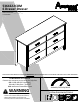
5364222COM 6 Drawer Dresser B345364222COM0 Date of Purchase ___ / ___ / ___ Lot Number: THIS INSTRUCTION BOOKLET CONTAINS IMPORTANT SAFETY INFORMATION. PLEASE READ AND KEEP FOR FUTURE REFERENCE. Do Not Return This Product! Contact our customer service team for help first. Call: 1‐800‐489‐3351 (toll free) Monday‐Friday 9am ‐ 5pm CST Visit: www.ameriwoodhome.com WARNING ‐ Unit can tip over causing severe injury or death. ‐ Anchor unit to stud in wall (if instructed to).
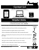
Contact Us! Do NOT return this product! Contact our friendly customer service team first for help. Assembly Tips Call us! 1‐800‐489‐3351 Monday‐Friday 9am ‐ 5pm CST Visit ameriwoodhome.com to view the limited warranty valid in the U.S. and Canada. You Tube Helpful Hints PEOPLE NEEDED FOR ASSEMBLY: 1‐2 ESTIMATED ASSEMBLY TIME: 2 HOURS ‐ Open your item in the area you plan to keep it to avoid excessive heavy lifting. ‐ Identify, sort and count the parts before attempting assembly.
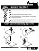
k Quic bly em Ass Ti p Before You Start Read through each step carefully and follow the proper order Separate and count all your parts and hardware Give yourself enough room for the assembly process Have the following tools: Flat Head Screwdriver, #2 Phillips Head Screwdriver and Hammer Caution: If using a power drill or power screwdriver for screwing, please be aware to slow down and stop when screw is tight. Failure to do so may result in stripping the screw.
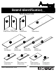
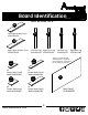
Board Identification Not actual size C B A D Right Panel Left Panel 35364222010 35364222020 F E Bottom 35364000050 Top 35364222040 Partition 35364222030 Top Rail 35364222060 I x2 Left Drawer Front 35364222090 ameriwoodhome.
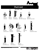
Board Identification Not actual size M Left UpperDrawer Front 35364222130 O P R Q N Right Upper Drawer Front 35364222140 DWR SIDE x4 Drawer Side (small) 39991120346200C DWR SIDE x8 Drawer Side (large) 39991167346200C ameriwoodhome.com Left Front Leg Right Front Leg 35364222150 35364222160 Left Rear Leg 35364222170 Right Rear Leg 35364222180 This piece is paperboard construction. It is not made from wood, but is required for the assembly of your unit.
Board Identification This piece is paperboard construction. It is not made from wood, but is required for the assembly of your unit. D F R S H A B P C E Q G DWR SIDE O DWR BACK DWR BACK K K M DWR SIDE L Left Upper Drawer N DWR SIDE DWR SIDE L K Right Upper Drawer DWR SIDE DWR BACK DWR BACK DWR SIDE DWR SIDE K I L ameriwoodhome.
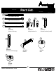
Part List Actual Size 2 3 1 (x18) #A22570 cam lock 5 4 (x18) #A22510 cam bolt (x12) #A21660 wood dowel (x60) #A11080 #6 x 7/16" flat head (x74) #A12120 #8 x 7/16" pan head 10 6 7 9 8 (x12) #A22910 connector bolt (x12) #A22920 connector (x8) #A53600 angle bracket 13 12 11 (x12) #A17400 8‐32 x 7/8" truss (x36) #A21970 drive fastener ameriwoodhome.
Part List 14a Left Cabinet Member 14b Right Cabinet Member 16 15c 15a 15d 14c 15b Left Drawer Member 14d Right Drawer Member (x6) #A56750 (x1) #A84050 safety bracket kit drawer slide pkg. (x4) #A54510 drawer bracket (small) 19 17 18 (x8) #A54520 drawer bracket (large) (x6) #A52925 handle (x1) #43100 foot 20 (x3) #43490 spacer ameriwoodhome.
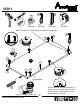
STEP 1 3 2 1 (x2) #A22570 (x3) #A22510 (x2) #A21660 7 (x6) #A22920 Note: Cam bolts (2) screw into the outside hole of each pair. 2 7 2 7 1 7 7 A 2 1 3 7 7 finished edge Quick Assembly Tip 3 Proper orientation of CAM LOCK ameriwoodhome.com You will need to tap the connector (7) with a hammer to fully insert. Be sure the connector is positioned as shown before tapping into hole.
STEP 2 1 (x2) #A22570 7 3 2 (x3) #A22510 (x2) #A21660 (x6) #A22920 Note: Cam bolts (2) screw into the outside hole of each pair. 2 2 7 7 1 7 7 B 2 7 7 1 3 finished edge Quick Assembly Tip You will need to tap the connector (7) with a hammer to fully insert. Be sure the connector is positioned as shown before tapping into hole. ameriwoodhome.
STEP 3 6 (x12) #A22910 Note: The rear legs (Q&R) have small pilot holes on the back surface. 6 6 6 6 6 R 6 6 Q 6 O P ameriwoodhome.
STEP 4 Press legs (O&Q) against the left panel (A) as shown so the connector bolt (6) engages the connector (7). Turn the screw in the center of the connector (7) clockwise to lock in place. 7 6 Turn screw to lock in place. 7 Q A O Note: For ease of leg attachment, place a piece of end foam (packaging material) under both ends of the left panel (A). A end view Q O Packaging foam from carton. ameriwoodhome.
STEP 5 14a 4 marked with a "L" Left Cabinet Member (x9) #A11080 (x3) #A56750 14a A 14a 14a 4 14a ameriwoodhome.
STEP 6 Press legs (P&R) against the right panel (B) as shown so the connector bolt (6) engages the connector (7). Turn the screw in the center of the connector (7) clockwise to lock in place. 7 6 Turn screw to lock in place. 7 R B P Note: For ease of leg attachment, place a piece of end foam (packaging material) under both ends of the right panel (B). B end view P Packaging foam from carton. ameriwoodhome.
STEP 7 marked with a "R" 14b 4 Right Cabinet Member (x9) #A11080 (x3) #A56750 14b 14b 14b 4 14b ameriwoodhome.
STEP 8 marked with a "L" 14a 3 1 Left Cabinet Member 4 marked with a "R" 14b Right Cabinet Member (x2) #A22570 (x2) #A21660 (x3) #A56750 (x18) #A11080 Quick Assembly 1 Tip Proper orientation of CAM LOCK 14a right surface C 1 14a 4 14a finished edge 3 14a 3 14b left surface C 4 14b 14b 14b ameriwoodhome.
STEP 9 15a 2 (x6) #A22510 5 8 (x8) #A12120 15b #A84050 safety bracket kit (x4) #A53600 2 5 2 8 5 2 F finished edge 2 D 2 15b 15a 2 ameriwoodhome.
STEP 10 Quick 3 Assembly Tip 1 (x4) #A22570 Proper orientation of CAM LOCK (x4) #A21660 1 3 1 1 E 1 3 3 ameriwoodhome.
STEP 11 5 8 (x4) (x8) #A53600 #A12120 Turn the part over from the previous step so the top surface faces up. Note, the bottom surface has the cam locks (1) in it. Do not fully tighten the screws (5) going into the bottom rail (G) at this time. finished edge 5 8 5 G E Cam locks (1) in bottom surface. ameriwoodhome.
STEP 12 Quick 3 Assembly Tip 1 (x2) #A22570 Proper orientation of CAM LOCK (x2) #A21660 1 3 1 H 3 ameriwoodhome.
STEP 13 13 (x2) #A23030 finished edge C G E 13 ameriwoodhome.
STEP 14 UNLOCK A C E ameriwoodhome.
STEP 15 Note: Support (H) with fit into notch of the partition (C). A UNLOCK H finished edge C E ameriwoodhome.
STEP 16 UNLOCK B H C E A ameriwoodhome.
STEP 17 19 20 UNLOCK LOCK (x3) #43490 (x1) #43100 Using a hammer, tap the spacers (20) and foot (19) into the bottom (E) as shown. A F C C E 20 B 19 Be sure the bottom rail (G) is positioned all the way up into the notch of the partition (C). Now tighten the screws that were left loose in step 11. ameriwoodhome.
STEP 18 5 9 (x24) (x10) #A21110 #A12120 IMPORTANT! THE BACK PANEL IS A STRUCTURAL PART OF THIS UNIT AND MUST BE INSTALLED PROPERLY. Positon back panel as shown. Align squarely with outer edges. Attach back panel to rear legs (O&P) with screws (5) but do not tighten. Flush bottom edge of back panel with bottom edge of the bottom and nail straight into back edges of top (C) and bottom (D). Now tighten the screws (5). 9 5 Back panel notch location. 5 Assure that the unit is square.
STEP 19 2 17 16 5 (x6) #A22510 (x24) #A12120 (x4) #A54510 (small) (x8) #A54520 (large) 5 5 17 5 I x2 5 5 2 16 J x2 5 17 2 M x1 N x1 5 5 16 Note: Small bracket (16) goes on the left and right upper drawer fronts (M&N) and large bracket (17) goes on the left and right drawer front (I&J). ameriwoodhome.
STEP 20 You will be assembling 6 drawers. Two smaller drawers (left and right uppers) and four larger drawers (left and right). The smaller drawer parts go with the smaller drawer fronts (M&N) and the larger with the larger drawer fronts (I&J). 5 (x24) #A12120 DWR SIDE 5 M x1 N x1 DWR SIDE DWR SIDE 5 5 5 I x2 J x2 5 DWR SIDE 5 5 Be sure the groove in the drawer side are centered with the groove in the drawer fronts. ameriwoodhome.
STEP 21 Quick 10 Assembly Tip 1 (x6) #A22570 Proper orientation of CAM LOCK (x6) #A21520 Tap compression dowel (10) lightly with a hammer to insert. 1 L x6 ameriwoodhome.
STEP 22 UNLOCK DWR SIDE L M x1 N x1 DWR SIDE DWR SIDE L DWR SIDE ameriwoodhome.
STEP 23 Insert the drawer bottom (K) into the groove of the drawer sides and drawer front as shown in all six drawers. unfinsihed surface K DWR SIDE L DWR SIDE x6 ameriwoodhome.
STEP 24 12 You will need to tap the drive fasteners (12) with a hammer to securely fasten. (x36) #A21970 Attached the drawer backs as shown. The two smaller drawer backs with go on the smaller drawers and the larger drawer backs go on the four larger drawers. 12 12 12 DWR SIDE DWR BACK 12 12 DWR SIDE ameriwoodhome.
STEP 25 11 14c 18 4 Left Drawer Member 14d (x24) #A11080 (x12) #A17400 Right Drawer Member (x6) #A56750 (x6) #52925 marked with a "R" 4 Attach the slide first then the handle. marked with a "L" DWR SIDE 11 DWR SIDE 4 11 x6 14c 18 ameriwoodhome.
STEP 26 For Masonry, Concrete, or other wall materials: Consult your local hardware store for appropriate anchors to securely attach the safety bracket. 15c 15d #A84050 safety bracket kit IMPORTANT: THIS UNIT MUST BE SECURE TO THE WALL TO HELP PREVENT TIPOVER. FOLLOW THESE INSTRUCTIONS TO INSTALL THE ANTI‐TIPPING SAFETY BRACKET PROVIDED WITH THIS PRODUCT. WARNING hole Serious or fatal crushing injuries can occur from furniture tipover.
STEP 27 Note: The drawer bracket holes are slotted. Drawer fronts can be adjusted by loosening screws, making needed adjustments and retightening screws. Install the drawers in the positions shown. N J J M I I cabinet member roller drawer runner roller ameriwoodhome.
Maximum Loads This unit has been designed to support the maximum loads shown. Exceeding these load limits could cause sagging, instability, product collapse, and/or serious injury. 75 lbs 34 kg 35 lbs 15.8 kg (each drawer) Warning: Risk of injury to persons ‐ do not place a television on this furniture. This furniture is not approved for use with a television. Certificate of Conformity 1. This certificate applies to the Dorel Home Furnishings, Inc. product identified by this instruction manual. 2.
Register your product to receive the following: * New trend details ‐ sneak peek on what's new * Surveys ‐ have a voice within our community * Exclusive deals and discount codes * Quick and easy replacement part service To register your product, visit ameriwoodhome.
Español Cubierta Delantera Este libro de instrucciones contiene información IMPORTANTE de seguridad. Por favor lea y manténgalo para referencia en el futuro. No Regrese este producto! Comuniquese con nuestro amistoso equipo de servicio al cliente para obtener ayuda. Llamenos al: 1‐800‐489‐3351 (Gratis) Lunes ‐ Viernes 9am ‐ 5pm CST Visitar: www.ameriwoodhome.com PRECAUCION Este mueble puede volcarse y causar graves heridas y/o muerte. Anclar el mueble a un poste de madera en la pared (si esto se requiere).
Español Páginas 9 Nota: Coloque los pernos (2) en el agujero exterior de cada par. Necesitará golpear el conector (7) con un martillo para insertarlo por completo. Asegúrese de que el conector esté posicionado como muestra la imagen antes de situarlo en el agujero. Páginas 10 Nota: Coloque los pernos (2) en el agujero exterior de cada par. Necesitará golpear el conector (7) con un martillo para insertarlo por completo.
Español Pagina 19 Dele la vuelta desde el paso anterior para que la superficie principal esté mirando hacia arriba. Tenga en cuenta que la superficie inferior tiene las cerraduras (1) en ella. Esta vez, no apriete los tornillos (5) por completo en el carril inferior (G). Cerraduras (1) en la superficie inferior. Página 23 Nota: Apóyelo (H) fijamente en la muesca de la partición (C). Página 25 Mediante un martillo, golpee los separadores (20) y la base (19) en la parte inferior (E), tal y como se muestra.
Español Página 28 Tendrá que montar los seis cajones: los dos cajones más pequeños (los superiores situados a la izquierda y a la derecha) y los cuatro más grandes (izquierda y derecha). Las partes más pequeñas del cajón van con las partes frontales pequeñas del cajón (M y N), y las partes más grandes van con las partes frontales grandes del cajón (I y J). Asegúrese de que las ranuras en los lados del cajón estén alineadas con las ranuras de la parte frontal del cajón.
Español El uso de los dispositivos contra caídas puede reducir, pero no eliminar por completo el riesgo de que el mueble se vuelque. OPCIÓN 1: acoplado a un travesaño de la pared (método recomendado) Ubica un travesaño en la pared utilizando un localizador de travesaños. Coloca tu unidad contra la pared, con el soporte de seguridad alineado en ese lugar.
Français Couverture Avant CE LIVRET D'INSTRUCTION CONTIENT DES INFORMATIONS IMPORTANTES SUR LA SÉCURITÉ. VEUILLEZ LIRE ET GARDER POUR UNE RÉFÉRENCE FUTURE Ne retournez pas ce produit! Contactez notre équipe de service à la clientèle amicale d'abord pour obtenir de l'aide. Appelez‐nous: 1‐800‐489‐3351 (sans frais) du Lundi au Vendredi de 9h à 17h Heure Centrale Visitez: www.ameriwoodhome.com ATTENTION Le meuble peut basculer et causer des blessures graves ou la mort.
Français Page 10 Note : les pênes battants (2) se visse dans l'intérieur du trou de chaque paire. Vous aurez besoin d'enfoncer le connecteur (7) avec un marteau pour l'insérer entièrement. Assurez‐vous que le connecteur soit positionné comme indiqué avant de l'enfoncer dans le trou. Page 11 Note : les pieds arrières (Q et R) ont de petits avant‐trous sur la surface arrière.
Français Page 23 Note : le support (H) ira dans l'encoche de la cloison (C). Page 25 En utilisant un marteau, enfoncez les entretoises (20) et le pied (19) dans le fond (E) comme indiqué. Assurez‐vous que le rail du fond (G) soit positionné jusqu'en haut dans l'encoche de la cloison (C ). Resserrez maintenant les vis qui ne l'étaient pas dans l'étape 11. Page 26 IMPORTANT! L'ARRIÈRE DU PANNEAU EST UN ÉLÉMENT STRUCTUREL DE CE MEUBLE ET DOIT ÊTRE INSTALLÉ CORRECTEMENT.
Français Page 32 Vous allez devoir enfoncer les fixations (12) avec un marteau pour les fixer fermement. Fixez les arrières des tiroirs comme indiqué. L'arrière des deux tiroirs plus petits va avec les tiroirs plus petits et l'arrière des tiroirs plus grands va avec les quatre tiroirs plus grands. Page 33 Fixez la glissière en premier, puis la poignée.
Français Page 35 Note : les trous de support du tiroir sont emboîtés. L'avant des tiroirs peut être ajusté en desserrant les vis, en faisant les ajustements nécessaires, puis en resserrant les vis. Installez les tiroirs dans les positions indiquées. Page 36 CHARGES MAXIMALES Ce meuble a été conçu pour supporter les charges maximales indiquées. En excédant ces limites de charge, le meuble pourrait devenir instable, s'effondrer, et/ou causer des blessures graves.