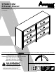
5758337COM 6 Drawer Dresser B345758337COM0 Date of Purchase ___ / ___ / ___ Lot Number: THIS INSTRUCTION BOOKLET CONTAINS IMPORTANT SAFETY INFORMATION. PLEASE READ AND KEEP FOR FUTURE REFERENCE. Do Not Return This Product! Contact our customer service team for help first. Call: 1‐800‐489‐3351 (toll free) Monday‐Friday 9am ‐ 5pm CST Visit: www.ameriwoodhome.com WARNING ‐ Unit can tip over causing severe injury or death. ‐ Anchor unit to stud in wall (if instructed to).
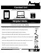
Contact Us! Do NOT return this product! Contact our friendly customer service team first for help. Assembly Tips Call us! 1‐800‐489‐3351 Monday‐Friday 9am ‐ 5pm CST Visit ameriwoodhome.com to view the limited warranty valid in the U.S. and Canada. You Tube Helpful Hints PEOPLE NEEDED FOR ASSEMBLY: 1‐2 ESTIMATED ASSEMBLY TIME: 2 HOUR ‐ Open your item in the area you plan to keep it to avoid excessive heavy lifting. ‐ Identify, sort and count the parts before attempting assembly.
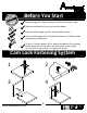
k Quic bly em Ass Ti p Before You Start Read through each step carefully and follow the proper order Separate and count all your parts and hardware Give yourself enough room for the assembly process Have the following tools: Flat Head Screwdriver, #2 Phillips Head Screwdriver and Hammer Caution: If using a power drill or power screwdriver for screwing, please be aware to slow down and stop when screw is tight. Failure to do so may result in stripping the screw.
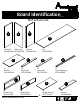
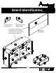
Board Identification Not actual size A C B D Right Panel Left Panel 35758337010 35758337020 Top 35758337040 Partition 35758337030 F E x2 Bottom 35758337050 x2 Upper Rail 35757337060 H G x2 Lower Rail 35757337070 x2 Vertical Molding 35758337080 K L I J x6 Drawer Front 35757337090 x6 Drawer Back 35757331100 ameriwoodhome.
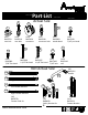
Board Identification Not actual size Y Z x6 Left Drawer Side 35781331250 S x6 Right Drawer Side 35781331260 This piece is paperboard construction. It is not made from wood, but is required for the assembly of your unit. D Back Panel K575800000 F L S F L A B H C E Z J G E K Y G H ameriwoodhome.
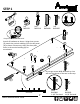
Part List 2 Actual Size 3 4 1 (x22) #A22570 cam lock (x22) #A22510 cam bolt (x12) #A22920 connector 8 (x12) #A22910 connector bolt (x24) #A11600 1‐1/4" flat head 6 (x11) #A21660 wood dowel (x24) #A12120 7/16" pan head 11 9 7 (x60) #A11080 7/16" flat head 5 10 (x6) #A12955 1‐1/8" flat head (x12) #A17100 7/16" bolt Not Actual Size (x44) #A21110 nail (x6) #A50515 Handle 13a Left Cabinet Member 15 13b Right Cabinet Member 13c Left Drawer Member 14c 14a 16 14d 13d 14b Right Draw
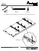
STEP 1 2 Quick Assembly 9 5 1 (x2) #A22570 (x4) #A22510 (x1) #A21660 (x3) #A12955 Tip 2 Proper orientation of CAM LOCK Attach all hardware as shown. Using three screws (9), attach the vertical molding (H) to the left panel (A) as shown. Please note, there are three pilot holes in the vertical molding (H) for attachment. 1 2 2 2 9 A 9 1 9 H 5 Do not get screws #8 & #9 mixed up. You will use the shorter of the two in this step. 8 9 end view ameriwoodhome.
STEP 2 7 13a Left Cabinet Member (x3) #A56770 (x9) #A11080 Attached three left cabinet members (13a) to the left panel (A) with screws (7) as shown. 13a A 13a 13a 7 Marked with a "L". 13a ameriwoodhome.
STEP 3 2 (x2) #A22570 Quick Assembly Tip 9 5 1 (x4) #A22510 (x1) #A21660 (x3) #A12955 Attach all hardware as shown. Using three screws (9), attach the vertical molding (H) to the right panel (B) as shown. Please note, there are three pilot holes in the vertical molding (H) for attachment. Proper orientation of CAM LOCK 2 2 9 1 2 2 9 B H 1 Do not get screws #8 & #9 mixed up. You will use the shorter of the two in this step.
STEP 4 13b Right Cabinet Member 7 (x9) #A11080 (x3) #A56770 Attach three right cabinet members (13b) to the right panel (B) with screws (7) as shown. 13b 13b B 13b 7 Marked with a "R". 13b ameriwoodhome.
STEP 5 2 5 1 (x2) #A22570 Quick Assembly (x8) #A22510 (x1) #A21660 Tip Proper orientation of CAM LOCK 5 1 2 2 2 2 C C right surface left surface 2 2 2 2 finished edge ameriwoodhome.
STEP 6 13a 7 Left Cabinet Member 13b (x18) #A11080 Right Cabinet Member (x3) #A56770 C C left surface Marked with a "R". 13b right surface 13b 13a 13b 13a 13b 13a Marked with a "L". finished edge 7 ameriwoodhome.
STEP 7 2 14a 4 14b (x6) #A22510 (x6) #A22910 (x1) #A84050 14b Do not tighten this screw. 14a 2 2 2 4 2 4 2 4 4 D 4 4 ameriwoodhome.
STEP 8 3 (x6) #A22920 3 3 3 F x2 You will need to tap the connector (3) with a hammer to fully insert. Be sure the connector is positioned as shown before pushing into hole. ameriwoodhome.
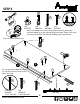
STEP 9 Press the two upper rails (F) onto the top (C) as shown so the connectors (3) engage the connector bolts (4). Turn the screw in the center of the connector (3) clockwise to lock in place. F F D 3 Turn clockwise to lock in place. ameriwoodhome.
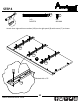
STEP 10 3 4 1 (x8) #A22570 (x6) #A22920 (x6) #A22910 5 (x4) #A21660 Quick Assembly Tip You will need to tap the connector (3) with a hammer to fully insert. Be sure the connector is positioned as shown before pushing into hole. Proper orientation of CAM LOCK 1 5 1 3 E x2 3 4 3 4 G 5 ameriwoodhome.
STEP 11 Press the lower rail (G) onto the bottom (D) as shown so the connector bolts (4) engage the connectors (3). Turn the screw in the center of the connector (3) clockwise to lock in place. G E 3 x2 Turn clockwise to lock in place. end view ameriwoodhome.
STEP 12 Assembly 5 1 (x8) #A22570 Quick Tip (x4) #A21660 Proper orientation of CAM LOCK 5 1 1 L x2 5 ameriwoodhome.
STEP 13 UNLOCK LOCK Press the bottom (E) and support (L) onto the right surface of the partition (C) as shown. Turn the cam locks (1) clockwise to lock in place. C right surface L E ameriwoodhome.
STEP 14 UNLOCK LOCK Press the bottom (E) and support (L) onto the left surface of the partition (C) as shown. Turn the cam locks (1) clockwise to lock in place. L C left surface E L E ameriwoodhome.
STEP 15 UNLOCK LOCK Press the left panel (A) and right panel (B) onto the bottom (E) and support (L) as shown. Turn the cam locks (1) clockwise to lock in place. B L C E L A ameriwoodhome.
STEP 16 UNLOCK LOCK With the help of another person, press the top (D) onto the left panel (A), right panel (B) and partition (C) as shown. Turn the cam locks (1) clockwise to lock in place. B C D A ameriwoodhome.
STEP 17 11 (x44) #A21110 IMPORTANT! THE BACK PANEL IS A STRUCTURAL PART OF THIS UNIT AND MUST BE INSTALLED PROPERLY. With the help of another person, turn the unit over as shown. Position the back panel (S) as shown. Flush the bottom edge of the back panel with the edge of the bottom (E). Assure that the unit is square. Distance from corner to corner must be equal as shown. Nail straight into back edges as shown. notch location 11 S ameriwoodhome.
STEP 18 16 (x12) #A54223 Lay the drawer sides down on a flat hard surface. Carefully line up the drawer bracket with the holes in the drawer side as shown. Using a hammer, tap each drawer bracket stem part way into the hole. Repeat this process until the drawer bracket is fully seated on the drawer side. 16 Y x6 ameriwoodhome.
STEP 19 6 (x24) #A12120 You will be assembling six drawers. They all assemble in the same manner. Attach the left drawer side (Y) and right drawer side (Z) to the Drawer Front (I) with screws (6) as shown. Be sure the groove in the drawer sides are centered with the groove in the drawer front. 6 Z Y I x6 ameriwoodhome.
STEP 20 Slide the drawer bottom (K) into the groove of the drawer sides (Y&Z) and drawer front (I). Z K finished surface Y I x6 ameriwoodhome.
STEP 21 8 8 (x24) #A11600 8 J Z K Y I x6 ameriwoodhome.
STEP 22 13c 7 10 13d (x24) #A11080 Left Drawer Member 15 Right Drawer Member (x12) #A17100 (x6) #A56770 Drawer Slide Kit Marked with a "R". (x6) #A50515 7 10 Z 13d 15 Y I x6 7 13c Marked with a "L". ameriwoodhome.
STEP 23 For Masonry, Concrete, or other wall materials: Consult your local hardware store for appropriate anchors to securely attach the safety bracket. 14c 14d (x1) #A84050 IMPORTANT: THIS UNIT MUST BE SECURE TO THE WALL TO HELP PREVENT TIPOVER. FOLLOW THESE INSTRUCTIONS TO INSTALL THE ANTI‐TIPPING SAFETY BRACKET PROVIDED WITH THIS PRODUCT. WARNING Serious or fatal crushing injuries can occur from furniture tipover.
STEP 24 Note: The drawer bracket holes are slotted. Drawer fronts can be adjusted by loosening screws, making needed adjustments and retightening screws. cabinet member roller drawer runner roller ameriwoodhome.
Maximum Loads This unit has been designed to support the maximum loads shown. Exceeding these load limits could cause sagging, instability, product collapse, and/or serious injury. 75 lbs 34 kg 35 lbs 15.8 kg (each drawer) Warning: Risk of injury to persons ‐ do not place a television on this furniture. This furniture is not approved for use with a television. Certificate of Conformity 1. This certificate applies to the Dorel Home Furnishings, Inc. product identified by this instruction manual. 2.
Register your product to receive the following: * New trend details ‐ sneak peek on what's new * Surveys ‐ have a voice within our community * Exclusive deals and discount codes * Quick and easy replacement part service To register your product, visit ameriwoodhome.
Español Cubierta Delantera Este libro de instrucciones contiene información IMPORTANTE de seguridad. Por favor lea y manténgalo para referencia en el futuro. No Regrese este producto! Comuniquese con nuestro amistoso equipo de servicio al cliente para obtener ayuda. Llamenos al: 1‐800‐489‐3351 (Gratis) Lunes ‐ Viernes 9am ‐ 5pm CST Visitar: www.ameriwoodhome.com PRECAUCION Este mueble puede volcarse y causar graves heridas y/o muerte. Anclar el mueble a un poste de madera en la pared (si esto se requiere).
Español Página 7 Nota: Los agujeros del soporte de la gaveta son ranurados. Los frontales de la gaveta se pueden ajustar aflojando los tornillos, hacienda los ajustes necesarios y volviendo a apretar los tornillos. vista final Página 8 Acople tres miembros del gabinete izquierdo (13a) al panel izquierdo (A) con tornillos (7) como se muestra. Marcado con una "L". Página 9 Acople todos los elementos como se muestra.
Español Página 17 Presione el riel inferior (G) sobre la parte inferior (D) como se muestra de manera que los conectores (4) se enganchen con los pernos de conexión (3). Gire el tornillo en el centro del conector (3) en sentido de las agujas del reloj para asegurarlo en su sitio. Gire en sentido de las agujas del reloj para asegurar en su lugar. vista final Página 19 Presione la parte inferior (E) y soporte (L) sobre la superficie derecha de la partición (C) como se muestra.
Español Página 24 Recueste los laterales de la gaveta sobre una superficie plana y dura. Con cuidado, alinee el soporte de la gaveta con los agujeros en el lateral de la misma, como se muestra. Usando un martillo, golpee suavemente cada vástago del soporte de la gaveta para que entre en el agujero. Repita este proceso hasta que el soporte de la gaveta esté completamente asentado en el lateral de la misma. Página 25 Usted ensamblará seis gavetas. Todas ellas se ensamblan de la misma manera.
Español OPCIÓN 1: Sujeción a una viga en la pared (método preferido) Usando un detector de vigas, ubique una en la pared. Coloque su unidad contra la pared, con el soporte de seguridad alineado en dicha ubicación. Para facilitar la inserción del tornillo, usted podría perforar un agujero piloto de 1/8" (3mm) de diámetro a través del soporte de seguridad y dentro de la viga. Inserte el tornillo a través del soporte de seguridad y dentro de la viga.
Français Couverture Avant CE LIVRET D'INSTRUCTION CONTIENT DES INFORMATIONS IMPORTANTES SUR LA SÉCURITÉ. VEUILLEZ LIRE ET GARDER POUR UNE RÉFÉRENCE FUTURE Ne retournez pas ce produit! Contactez notre équipe de service à la clientèle amicale d'abord pour obtenir de l'aide. Appelez‐nous: 1‐800‐489‐3351 (sans frais) du Lundi au Vendredi de 9h à 17h Heure Centrale Visitez: www.ameriwoodhome.com ATTENTION Le meuble peut basculer et causer des blessures graves ou la mort.
Français Page 8 Joindre trois parties de gauche de l'armoire (13a) au panneau gauche (A) avec les vis (7) comme indiqué. Marqués par un « L ». Page 9 Relier toutes les parties du meuble tel qu'illustré. À l'aide de trois vis (9), fixer le moulage vertical (H) au panneau droit (B) comme indiqué. Remarque : le moulage vertical (H) comporte trois trous de guidage pour la fixation. Vue arrière Page 10 Fixer les trois pièces de droite de l'armoire (13b) au panneau droit (B) avec les vis (7) comme indiqué.
Français Page 19 Appuyer ensemble la partie inférieure (E) et le support (L) sur la surface droite de la partition (C) comme illustré. Tourner les verrous à came (1) dans le sens horaire pour verrouiller. Surface de droite Page 20 Appuyer ensemble la partie inférieure (E) et le support (L) sur la surface droite de la partition (C) comme illustré. Tourner les verrous à came (1) dans le sens horaire pour verrouiller.
Français Page 26 Faire glisser le fond du tiroir (K) dans la rainure des côtés du tiroir (Y et Z) ainsi que la face avant du tiroir (I). Surface finie Page 29 Pour la maçonnerie, le béton ou d'autres matériaux de mur : Visiter votre quincaillerie locale pour obtenir des ancres appropriées qui permettront de fixer solidement le support de sécurité. IMPORTANT : CE MEUBLE DOIT ÊTRE SÉCURISÉ SUR LE MUR POUR ÉVITER QU'IL NE BASCULE.
Français Page 30 Avant d'installer les tiroirs, placer les couvercles de vis (12) sur les têtes de vis qui serrent les moulures verticales (H) et appuyer sur les têtes. Utiliser un marteau pour fixer en toute sécurité le cas échéant. Remarque : les trous du support de tiroir sont encastrés. Les faces avant du tiroir peuvent être ajustées en desserrant les vis, en effectuant les réglages nécessaires et en resserrant les vis.