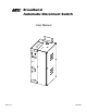
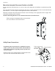
Broadband Automatic Disconnect Switch User Manual Loca l Pow er Re mo te Pw er Rese t/Test Loca l 63V Fault Prima ry/ Seco nda ry Se lec t Prim ary Se con dary 220V No rm al 990-1929 09/2004
Introduction Introduction About this unit Redundant power and output voltage monitoring for Broadband cable systems is provided with the use of two APC Automatic Disconnect Switches and two Ferroresonant Power Supplies (FRP). Safety Electrical Warnings Do not work alone under hazardous conditions. High current through conductive materials could cause severe burns. Do not work alone under hazardous conditions. High current through conductive materials could cause severe burns.
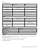
Installation Electrical Specifications Utility Power Cable Input Connection Three Position Terminal Block Cable Adapter (5/8-24) Terminal Block to Coax Center Conductor Nominal Voltage 220 V 63 V Allowable Input range 165-270 V 40-75 V Maximum Current 15 A 18 A Input Current Limiting 10 A N/A Three Position Terminal Block Cable Adapter (5/8-24) Terminal Block to Coax Center Conductor I Output Connection Allowable Output range 40-75 V Initial Connection Delay Primary - None Secondary -
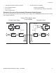
Installation • • • • Automatic Disconnect Switch enclosure Two mounting brackets Four screws One F Connector nut • UPS literature kit containing: – product documentation – safety information warranty information Schematic Overview of the Automatic Disconnect Switch System The user must designate the primary and secondary power supply. Refer to Reset/Test in the Operation section of this manual for details.
Installation Mount the Automatic Disconnect Switch on the Wall Do not operate the UPS where there is excessive dust or the temperature or humidity are outside the specified limits. The Automatic Disconnect Switch enclosure has side vents. To ensure adequate air flow in and around the unit there must be 1” (2.5 cm) of space on the right and left sides of the enclosure.
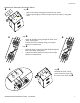
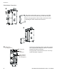
Installation Hardwire the Automatic Disconnect Switch Step • • Remove the utility wiring panel located on top of unit. When required apply a strain relief grommet to the utility wiring panel holes. Step • Route the building wiring through the holes in the utility wiring panel. • Connect the 220 V building wiring to the Input Hardwire terminal block. Step • • Route the input wiring for the FRP/FLM through the hole in the utility wiring panel.
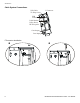
Installation Cable System Connections USB Cable Tie Wrap Lance F Connector USB Connector Cable Modem Utility Power IEC Recepticle Coax Output Coax Input F-Connector Installation 8 Broadband Automatic Disconnect Switch User Manual
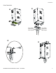
Installation Coax Connection Coax InputConnects to FRP Output Coax OutputConnects to Cable System Broadband Automatic Disconnect Switch User Manual 9
Installation Cable Modem Connection The cable modem utility power, F-connector, and USB connectors are located on the back of the cable modem. Secure the appropriate cables to these connectors before installing the cable modem in the enclosure. USB Cable Tie Wrap Lance Lo cal P o w er Rem ot e P o wer 10 F Connector Connect the appropriate cables to the cable modem IEC receptacle, the USB port, and the F-connector located on inside the enclosure.
Operation Start Up Primary/Secondary Access Panel To remove the access panel covering the Primary/Secondary Select button remove the screw that secures the panel to the enclosure. Slide the access panel slightly to the right and then pull the access panel toward you.
Operation Reset/Test: Functionality of this control is dependant upon Automatic Disconnect Switch status. Primary Status • The primary Automatic Disconnect Switch is supplying power to the cable system. The Local Power LED will be illuminated. The Reset/Test button will do nothing. • When the primary Automatic Disconnect Switch is not supplying power to the cable system the Remote Power LED will be illuminated.
Troubleshooting, Service, Contact, Warranty and Regulatory Information Troubleshooting, Service, Contact, Warranty and Regulatory Information Troubleshooting Use this chart to solve minor installation and operation problems. Refer to the APC Web, site www.apc.com with complex problems. Problem and/or Possible Cause Solution Unit is on and the 220 V Normal LED is not illuminated The unit is not wired properly. Check that the input and output wiring are not reversed. The circuit breaker is tripped.
Troubleshooting, Service, Contact, Warranty and Regulatory Information Service If the unit requires service do not return it to the dealer. Follow these steps: 1. Review the problems discussed in Troubleshooting to eliminate common problems. 2. If the problem persists, contact APC Customer Support through the APC Web site, www.apc.com. – Note the model number of the unit, the serial number, and the date purchased.