
User guide
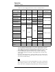

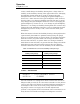
Table Of Contents
- Table of Contents
- List of Figures
- List of Tables
- Foreword
- 1 Introduction
- 1.1 Model 4Q1010PS-430 Integrated Power Supply System Features
- 1.1.1 Digitally-Controlled
- 1.1.2 Superior Resolution and Stability
- 1.1.3 Intuitive Human-Interface Design
- 1.1.4 Flexibility
- 1.1.5 Standard Remote Interfaces
- 1.1.6 Programmable Safety Features
- 1.1.7 Condition-Based Magnet Auto-Rampdown
- 1.1.8 Model 4Q1010PS-430 General Description
- 1.1.9 Power Supply System Rack Front Panel Layout
- 1.2 Model 430 Front Panel Layout
- 1.3 Model 430 Rear Panel Layout
- 1.4 Power Supply Unit Front Panel Layout
- 1.5 System Specifications @ 25 C
- 1.6 Operating Characteristics
- 1.1 Model 4Q1010PS-430 Integrated Power Supply System Features
- 2 Installation
- 3 Operation
- 3.1 System Power On/Off Sequence
- 3.2 Model 430 Programmer Default Display
- 3.3 Entering Numeric Values
- 3.4 Using Fine Adjust Knob to Adjust Numeric Values
- 3.5 Entering Picklist Values
- 3.6 Single-key Commands / Menu
- 3.7 SHIFT-key Commands / Menus
- Figure 3-5. SHIFT-Key Functions
- 3.7.1 Ramp Rate SHIFT-key
- 3.7.2 Voltage Limit SHIFT-key
- 3.7.3 Reset Quench SHIFT-key
- 3.7.4 Increment Field SHIFT-key
- 3.7.5 Field <> Current SHIFT-key
- 3.7.6 Decrement Field SHIFT-key
- 3.7.7 Field Units SHIFT-key
- 3.7.8 Persistent Switch Heater Current SHIFT-key
- 3.7.9 Stability SHIFT-key
- 3.7.10 Vs <> Vm SHIFT-key
- 3.7.11 Volt Meter SHIFT-key
- 3.7.12 Fine Adjust SHIFT-key
- 3.7.13 Persist. Switch Control SHIFT-key
- 3.8 LED Indicators
- 3.9 Setup Menu
- 3.10 Setup Submenu Descriptions
- Figure 3-7. Setup Menu Structure
- 3.10.1 Supply Submenu
- 3.10.2 Load Submenu
- 3.10.2.1 Stability Setting
- 3.10.2.2 Coil Constant
- 3.10.2.3 Magnet Current Rating
- 3.10.2.4 Current Limit
- 3.10.2.5 Calculate Magnet Inductance
- 3.10.2.6 PSwitch Installed
- 3.10.2.7 PSwitch Current Detect (mA)
- 3.10.2.8 PSwitch Current
- 3.10.2.9 PSwitch Heated Time
- 3.10.2.10 PSwitch Cooled Time
- 3.10.2.11 PSwitch Power Supply Ramp Rate
- 3.10.2.12 PSwitch Cooling Gain
- 3.10.2.13 Enable Quench Detect
- 3.10.2.14 Energy Absorber Present
- 3.10.2.15 Enable External Rampdown
- 3.10.3 Misc Submenu
- 3.10.4 Net Settings Submenu
- 3.10.5 Net Setup Submenu
- 3.11 Example Setup
- 3.12 Ramping Functions
- 3.13 Persistent Switch Control
- 3.14 Ramping Functions Example
- 3.15 Quench Detection
- 3.16 External Rampdown
- 3.17 Summary of Operational Limits and Default Settings
- 4 Remote Interface Reference
- 4.1 SCPI Command Summary
- 4.2 Programming Overview
- 4.3 RS-232 Configuration
- 4.4 Ethernet Configuration
- 4.5 Command Reference
- 4.5.1 System-Related Commands
- 4.5.2 Status System Commands
- 4.5.3 SETUP Configuration Commands and Queries
- 4.5.4 Protection Commands and Queries
- 4.5.5 Ramp Configuration Commands and Queries
- 4.5.6 Ramping State Commands and Queries
- 4.5.7 Switch Heater Command and Query
- 4.5.8 Quench State Commands and Queries
- 4.5.9 Rampdown State Queries
- 4.5.10 Trigger Functions
- 4.6 Error Messages
- 5 Service
- 5.1 System Component Maintenance
- 5.2 Troubleshooting Hints
- 5.2.1 Electrostatic Discharge Precautions
- 5.2.2 The Model 430 does not appear to be energized
- 5.2.3 FAILURE TO LOAD message displayed after power-up
- 5.2.4 Power supply unstable - magnet voltage oscillates
- 5.2.5 The power supply system will not charge the magnet.
- 5.2.6 Cannot charge the magnet at the selected ramp rate.
- 5.2.7 Cannot discharge the magnet at the selected ramp rate
- 5.2.8 Cannot charge the magnet to desired field.
- 5.2.9 Current in only one direction from 4-quadrant supply
- 5.2.10 Cannot place the magnet in persistent mode.
- 5.2.11 Cannot bring the magnet out of persistent mode.
- 5.2.12 The magnet quenches for no apparent reason
- 5.2.13 Cannot lower the magnet field
- 5.2.14 There is excessive LHe boil-off during operation.
- 5.2.15 Cannot display the magnetic field strength, only current
- 5.2.16 Cannot use remote communications commands.
- 5.2.17 Magnet current drifts unacceptably while PSwitch cooling
- 5.2.18 Model 430 appears to lock up when connecting to network
- 5.3 Additional Technical Support
- 5.4 Return Authorization
- Appendix
- A.1 Magnet Station Connectors
- A.2 LHe Level / Temp Connectors
- A.3 Programmer Shunt Terminals
- A.4 Program Out Connector
- A.5 Quench I/O Connector
- A.6 Aux Inputs Connector
- A.7 Ethernet Connector
- A.8 RS-232 Connector
- A.9 Abbreviations and Acronyms used in this Manual
- A.10 Model 430 Programmer Specifications
- A.11 Power Supply Details
- A.12 Remote Computer Communication with the Model 430
- A.13 Upgrading the Model 430 Firmware via FTP
- A.14 Upgrading the Model 430 Firmware via Flash Card Reader
- A.15 Model 430 Remote Control Application
- A.16 Model 430IP Power Supply Programmer
- A.17 Persistent Switch Operation Flowchart
- Index
Rev. 5 45
Operation
Setup Menu : Supply
Note
The current must be less than 0.1% of I
max
in order to change the
Select Supply picklist value. If a change is attempted with current
above this value, the Model 430 Programmer will beep and ignore
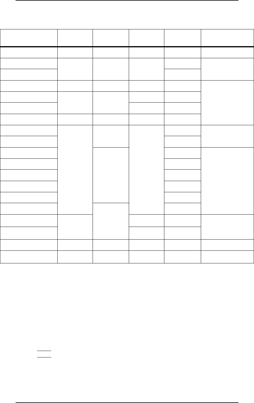
Table 3-2. Select Supply picklist values and associated parameters.
Power Supply
Min Output
Voltage (V)
Max Output
Voltage (V)
Min Output
Current (A)
Max Output
Current (A)
V-V Mode Input
Range (V)
AMI 08150PS 0 +8.000 +0.0000 +150.000 +0.000 to +10.000
AMI 12100PS
+0.000 +12.000 +0.000
+100.000
+0.000 to +10.000
AMI 12200PS +200.000
AMI 4Q05100PS −5.000 +5.000 −100.000 +100.000
−10.000 to +10.000
AMI 4Q06125PS
-6.000 +6.000
-125.000 +125.000
AMI 4Q06250PS -250.000 +250.000
AMI 4Q12125PS -12.000 +12.000 -125.000 +125.000
AMI 10100PS
+0.000
+10.000
+0.000
+100.000
+0.000 to +5.000
AMI 10200PS +200.000
AMI 05100PS
+10.000
a
+100.000
+0.000 to +10.000
AMI 05200PS +200.000
AMI 05300PS +300.000
AMI 05400PS +400.000
AMI 05500PS +500.000
HP 6260B
+10.000
+100.000
Kepco BOP 20-5M
b
−10.000
−5.000 +5.000
−10.000 to +10.000
Kepco BOP 20-10M
b
−10.000 +10.000
Xantrex XFR 7.5-140 +0.000 +7.500 +0.000 +140.000 +0.000 to +10.000
Custom...
c
−20.000 +20.000 −200.000 +200.000 −10.000 to +10.000
a. The individual 05100PS power supply unit will source +10.000 Vdc at 100 A. How-
ever, the standard configuration of this series of power supplies includes the Model
601 Energy Absorber to provide bipolar operation. The 05x00-430-601 series of
power supply systems provides a maximum available voltage to the load of ±5.000
Vdc at multiples of 100 A, up to 500 A depending on the system selected.
b. The Kepco BOP power supplies are limited to only one-half the output voltage
range since the supplies are designed to safely dissipate only one-half the rated
power output.
c. The values shown for the Custom... option are defaults. The user should enter the
appropriate values within the respective submenus. Custom values, once entered,
are saved in nonvolatile memory.