
User guide
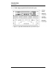
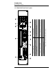
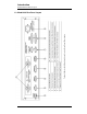
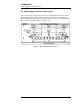
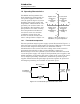

Table Of Contents
- Table of Contents
- List of Figures
- List of Tables
- Foreword
- 1 Introduction
- 1.1 Model 4Q1010PS-430 Integrated Power Supply System Features
- 1.1.1 Digitally-Controlled
- 1.1.2 Superior Resolution and Stability
- 1.1.3 Intuitive Human-Interface Design
- 1.1.4 Flexibility
- 1.1.5 Standard Remote Interfaces
- 1.1.6 Programmable Safety Features
- 1.1.7 Condition-Based Magnet Auto-Rampdown
- 1.1.8 Model 4Q1010PS-430 General Description
- 1.1.9 Power Supply System Rack Front Panel Layout
- 1.2 Model 430 Front Panel Layout
- 1.3 Model 430 Rear Panel Layout
- 1.4 Power Supply Unit Front Panel Layout
- 1.5 System Specifications @ 25 C
- 1.6 Operating Characteristics
- 1.1 Model 4Q1010PS-430 Integrated Power Supply System Features
- 2 Installation
- 3 Operation
- 3.1 System Power On/Off Sequence
- 3.2 Model 430 Programmer Default Display
- 3.3 Entering Numeric Values
- 3.4 Using Fine Adjust Knob to Adjust Numeric Values
- 3.5 Entering Picklist Values
- 3.6 Single-key Commands / Menu
- 3.7 SHIFT-key Commands / Menus
- Figure 3-5. SHIFT-Key Functions
- 3.7.1 Ramp Rate SHIFT-key
- 3.7.2 Voltage Limit SHIFT-key
- 3.7.3 Reset Quench SHIFT-key
- 3.7.4 Increment Field SHIFT-key
- 3.7.5 Field <> Current SHIFT-key
- 3.7.6 Decrement Field SHIFT-key
- 3.7.7 Field Units SHIFT-key
- 3.7.8 Persistent Switch Heater Current SHIFT-key
- 3.7.9 Stability SHIFT-key
- 3.7.10 Vs <> Vm SHIFT-key
- 3.7.11 Volt Meter SHIFT-key
- 3.7.12 Fine Adjust SHIFT-key
- 3.7.13 Persist. Switch Control SHIFT-key
- 3.8 LED Indicators
- 3.9 Setup Menu
- 3.10 Setup Submenu Descriptions
- Figure 3-7. Setup Menu Structure
- 3.10.1 Supply Submenu
- 3.10.2 Load Submenu
- 3.10.2.1 Stability Setting
- 3.10.2.2 Coil Constant
- 3.10.2.3 Magnet Current Rating
- 3.10.2.4 Current Limit
- 3.10.2.5 Calculate Magnet Inductance
- 3.10.2.6 PSwitch Installed
- 3.10.2.7 PSwitch Current Detect (mA)
- 3.10.2.8 PSwitch Current
- 3.10.2.9 PSwitch Heated Time
- 3.10.2.10 PSwitch Cooled Time
- 3.10.2.11 PSwitch Power Supply Ramp Rate
- 3.10.2.12 PSwitch Cooling Gain
- 3.10.2.13 Enable Quench Detect
- 3.10.2.14 Energy Absorber Present
- 3.10.2.15 Enable External Rampdown
- 3.10.3 Misc Submenu
- 3.10.4 Net Settings Submenu
- 3.10.5 Net Setup Submenu
- 3.11 Example Setup
- 3.12 Ramping Functions
- 3.13 Persistent Switch Control
- 3.14 Ramping Functions Example
- 3.15 Quench Detection
- 3.16 External Rampdown
- 3.17 Summary of Operational Limits and Default Settings
- 4 Remote Interface Reference
- 4.1 SCPI Command Summary
- 4.2 Programming Overview
- 4.3 RS-232 Configuration
- 4.4 Ethernet Configuration
- 4.5 Command Reference
- 4.5.1 System-Related Commands
- 4.5.2 Status System Commands
- 4.5.3 SETUP Configuration Commands and Queries
- 4.5.4 Protection Commands and Queries
- 4.5.5 Ramp Configuration Commands and Queries
- 4.5.6 Ramping State Commands and Queries
- 4.5.7 Switch Heater Command and Query
- 4.5.8 Quench State Commands and Queries
- 4.5.9 Rampdown State Queries
- 4.5.10 Trigger Functions
- 4.6 Error Messages
- 5 Service
- 5.1 System Component Maintenance
- 5.2 Troubleshooting Hints
- 5.2.1 Electrostatic Discharge Precautions
- 5.2.2 The Model 430 does not appear to be energized
- 5.2.3 FAILURE TO LOAD message displayed after power-up
- 5.2.4 Power supply unstable - magnet voltage oscillates
- 5.2.5 The power supply system will not charge the magnet.
- 5.2.6 Cannot charge the magnet at the selected ramp rate.
- 5.2.7 Cannot discharge the magnet at the selected ramp rate
- 5.2.8 Cannot charge the magnet to desired field.
- 5.2.9 Current in only one direction from 4-quadrant supply
- 5.2.10 Cannot place the magnet in persistent mode.
- 5.2.11 Cannot bring the magnet out of persistent mode.
- 5.2.12 The magnet quenches for no apparent reason
- 5.2.13 Cannot lower the magnet field
- 5.2.14 There is excessive LHe boil-off during operation.
- 5.2.15 Cannot display the magnetic field strength, only current
- 5.2.16 Cannot use remote communications commands.
- 5.2.17 Magnet current drifts unacceptably while PSwitch cooling
- 5.2.18 Model 430 appears to lock up when connecting to network
- 5.3 Additional Technical Support
- 5.4 Return Authorization
- Appendix
- A.1 Magnet Station Connectors
- A.2 LHe Level / Temp Connectors
- A.3 Programmer Shunt Terminals
- A.4 Program Out Connector
- A.5 Quench I/O Connector
- A.6 Aux Inputs Connector
- A.7 Ethernet Connector
- A.8 RS-232 Connector
- A.9 Abbreviations and Acronyms used in this Manual
- A.10 Model 430 Programmer Specifications
- A.11 Power Supply Details
- A.12 Remote Computer Communication with the Model 430
- A.13 Upgrading the Model 430 Firmware via FTP
- A.14 Upgrading the Model 430 Firmware via Flash Card Reader
- A.15 Model 430 Remote Control Application
- A.16 Model 430IP Power Supply Programmer
- A.17 Persistent Switch Operation Flowchart
- Index

Rev. 5 3
Introduction
General Description
1.1.8 Model 4Q1010PS-430 General Description
A Model 430 Power Supply Programmer and Kepco BOP series power
supply are configured to make up the system designated as 4Q1010PS-
430. The Model 4Q1010PS is a 100 Watt, ±10
1
Volt, ±10 ampere, 4-
quadrant, voltage and current stabilized DC supply. The power supply is
remotely controlled by the Model 430 Power Supply Programmer.
The Model 4Q1010PS-430 is a true 4-quadrant voltage and current power
supply capable of both sourcing and sinking
2
power smoothly through zero
to provide true ±voltage and ±current. It is ideal for controlling inductive
loads, such as small magnets or motors, with high precision.
The power supply is controlled by a ±10 Vdc remote analog signal supplied
by the Model 430 Programmer and applied to the power supply analog
input. Programming and control of the current loop (composed of the
magnet, power supply, and Model 430 Programmer shunt), is provided by
a Model 430 ramp-generated current reference with parameters as set by
the user in the Model 430. The Model 430 compares the measured current
(via the shunt) with the current reference to provide precise closed-loop
control of the actual current.
The power supply is operated in voltage-voltage
3
programming mode, with
the Model 430 Programmer output scaled to operate the power supply over
its available voltage output range. The Programmer signal will continually
adjust the power supply output voltage to automatically regulate the
power supply current; precise linear power supply current control will
result as long as the system voltage and current demand do not exceed the
power supply rating or load limiting parameters.
1. Due to continuous discharge power limitations present in the BOP series supplies,
for maximum safety AMI limits both the charging and discharging voltage to a max-
imum of 10 volts via the Model 430 Programmer, effectively limiting the available
power to 100 watts.
2. The power supply is operating as a source if the current direction and voltage polar-
ity are the same (i.e., the situation that would exist when supplying a resistive load).
If the voltage polarity and current direction are opposite, the supply is operating as
a sink and energy is being absorbed.
3. Voltage reference controlling voltage output.