
User guide
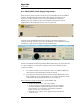
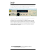
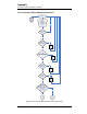
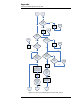
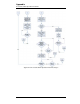

Table Of Contents
- Table of Contents
- List of Figures
- List of Tables
- Foreword
- 1 Introduction
- 1.1 Model 4Q1010PS-430 Integrated Power Supply System Features
- 1.1.1 Digitally-Controlled
- 1.1.2 Superior Resolution and Stability
- 1.1.3 Intuitive Human-Interface Design
- 1.1.4 Flexibility
- 1.1.5 Standard Remote Interfaces
- 1.1.6 Programmable Safety Features
- 1.1.7 Condition-Based Magnet Auto-Rampdown
- 1.1.8 Model 4Q1010PS-430 General Description
- 1.1.9 Power Supply System Rack Front Panel Layout
- 1.2 Model 430 Front Panel Layout
- 1.3 Model 430 Rear Panel Layout
- 1.4 Power Supply Unit Front Panel Layout
- 1.5 System Specifications @ 25 C
- 1.6 Operating Characteristics
- 1.1 Model 4Q1010PS-430 Integrated Power Supply System Features
- 2 Installation
- 3 Operation
- 3.1 System Power On/Off Sequence
- 3.2 Model 430 Programmer Default Display
- 3.3 Entering Numeric Values
- 3.4 Using Fine Adjust Knob to Adjust Numeric Values
- 3.5 Entering Picklist Values
- 3.6 Single-key Commands / Menu
- 3.7 SHIFT-key Commands / Menus
- Figure 3-5. SHIFT-Key Functions
- 3.7.1 Ramp Rate SHIFT-key
- 3.7.2 Voltage Limit SHIFT-key
- 3.7.3 Reset Quench SHIFT-key
- 3.7.4 Increment Field SHIFT-key
- 3.7.5 Field <> Current SHIFT-key
- 3.7.6 Decrement Field SHIFT-key
- 3.7.7 Field Units SHIFT-key
- 3.7.8 Persistent Switch Heater Current SHIFT-key
- 3.7.9 Stability SHIFT-key
- 3.7.10 Vs <> Vm SHIFT-key
- 3.7.11 Volt Meter SHIFT-key
- 3.7.12 Fine Adjust SHIFT-key
- 3.7.13 Persist. Switch Control SHIFT-key
- 3.8 LED Indicators
- 3.9 Setup Menu
- 3.10 Setup Submenu Descriptions
- Figure 3-7. Setup Menu Structure
- 3.10.1 Supply Submenu
- 3.10.2 Load Submenu
- 3.10.2.1 Stability Setting
- 3.10.2.2 Coil Constant
- 3.10.2.3 Magnet Current Rating
- 3.10.2.4 Current Limit
- 3.10.2.5 Calculate Magnet Inductance
- 3.10.2.6 PSwitch Installed
- 3.10.2.7 PSwitch Current Detect (mA)
- 3.10.2.8 PSwitch Current
- 3.10.2.9 PSwitch Heated Time
- 3.10.2.10 PSwitch Cooled Time
- 3.10.2.11 PSwitch Power Supply Ramp Rate
- 3.10.2.12 PSwitch Cooling Gain
- 3.10.2.13 Enable Quench Detect
- 3.10.2.14 Energy Absorber Present
- 3.10.2.15 Enable External Rampdown
- 3.10.3 Misc Submenu
- 3.10.4 Net Settings Submenu
- 3.10.5 Net Setup Submenu
- 3.11 Example Setup
- 3.12 Ramping Functions
- 3.13 Persistent Switch Control
- 3.14 Ramping Functions Example
- 3.15 Quench Detection
- 3.16 External Rampdown
- 3.17 Summary of Operational Limits and Default Settings
- 4 Remote Interface Reference
- 4.1 SCPI Command Summary
- 4.2 Programming Overview
- 4.3 RS-232 Configuration
- 4.4 Ethernet Configuration
- 4.5 Command Reference
- 4.5.1 System-Related Commands
- 4.5.2 Status System Commands
- 4.5.3 SETUP Configuration Commands and Queries
- 4.5.4 Protection Commands and Queries
- 4.5.5 Ramp Configuration Commands and Queries
- 4.5.6 Ramping State Commands and Queries
- 4.5.7 Switch Heater Command and Query
- 4.5.8 Quench State Commands and Queries
- 4.5.9 Rampdown State Queries
- 4.5.10 Trigger Functions
- 4.6 Error Messages
- 5 Service
- 5.1 System Component Maintenance
- 5.2 Troubleshooting Hints
- 5.2.1 Electrostatic Discharge Precautions
- 5.2.2 The Model 430 does not appear to be energized
- 5.2.3 FAILURE TO LOAD message displayed after power-up
- 5.2.4 Power supply unstable - magnet voltage oscillates
- 5.2.5 The power supply system will not charge the magnet.
- 5.2.6 Cannot charge the magnet at the selected ramp rate.
- 5.2.7 Cannot discharge the magnet at the selected ramp rate
- 5.2.8 Cannot charge the magnet to desired field.
- 5.2.9 Current in only one direction from 4-quadrant supply
- 5.2.10 Cannot place the magnet in persistent mode.
- 5.2.11 Cannot bring the magnet out of persistent mode.
- 5.2.12 The magnet quenches for no apparent reason
- 5.2.13 Cannot lower the magnet field
- 5.2.14 There is excessive LHe boil-off during operation.
- 5.2.15 Cannot display the magnetic field strength, only current
- 5.2.16 Cannot use remote communications commands.
- 5.2.17 Magnet current drifts unacceptably while PSwitch cooling
- 5.2.18 Model 430 appears to lock up when connecting to network
- 5.3 Additional Technical Support
- 5.4 Return Authorization
- Appendix
- A.1 Magnet Station Connectors
- A.2 LHe Level / Temp Connectors
- A.3 Programmer Shunt Terminals
- A.4 Program Out Connector
- A.5 Quench I/O Connector
- A.6 Aux Inputs Connector
- A.7 Ethernet Connector
- A.8 RS-232 Connector
- A.9 Abbreviations and Acronyms used in this Manual
- A.10 Model 430 Programmer Specifications
- A.11 Power Supply Details
- A.12 Remote Computer Communication with the Model 430
- A.13 Upgrading the Model 430 Firmware via FTP
- A.14 Upgrading the Model 430 Firmware via Flash Card Reader
- A.15 Model 430 Remote Control Application
- A.16 Model 430IP Power Supply Programmer
- A.17 Persistent Switch Operation Flowchart
- Index

Rev. 5 191
Index
A
abbreviations and acronyms 154
absolute limits 90
AMI internet e-mail address 143
AMI web address 143
B
beep
editing PSw P/S ramp rate 34
editing ramp rate 33
error messages 130
incorrect password 61, 68
locked command 61
mismatch between pswitch and power
supply currents 83
on initiate ramping 30
on select supply 45
on setting current limit below TARGET
FIELD SETPOINT 53
on setting magnet current rating below
TARGET FIELD SETPOINT
52
parameter outside range 26, 90
pswitch 29
pswitch did not properly transition to the
superconducting state 80
boot 177, 181
brightness 59
C
cable interconnections. See interconnects
cancelling entry 26
cleaning - see routine maintenance
closed-loop control 3
coil constant
acceptable values 51
calculate 51
defined 50
lock 65
command
error messages 130
device errors 132
query errors 131
in remote control application 184
overview 100
command handshaking 104
condition register 100
event register 101
SCPI introduction 100
standard event register 103
status byte 101
status system 100
status system diagram 101
reference
locking 115
protection commands 115
quench control 126
ramping commands 120
ramping states 124
setup commands 110
status commands 109
switch heater control 125
system commands 108
trigger commands 129
trigger functions 128
summary
conventions 93
protection commands 95
protection configuration queries 96
quench state 99
ramp configuration 98
ramping state 99
setup configuration commands 94
setup configuration queries 95
switch heater 99
system-related commands 93
trigger control 99
compatible power supplies 50
configuration
system
four-quadrant low-current supply
14
general 13
non-standard 17
power lead size 13
connectors
aux input 152
Ethernet communication 16, 153
LHe level/temp 13, 16, 146
magnet station 13, 16, 145
program out 16, 148
quench I/O 16, 149
RJ-45 - see Ethernet
RS-232 serial communication 16,
153
shunt terminals 147
system interconnect 13
current limit 20, 31, 33, 35, 37, 38,
43, 52, 61, 75, 77, 113,
124, 125
current limit example 52
current limit symmetry 53
current transducer
current direction 14
in dual quadrant system 9
in four-quadrant system 9
D
data logging 128
de-energizing the system 22
default display modes 22
default password 61
default settings 90
DHCP 70, 72, 169, 173
diode
light emitting - see LED
1Index