
User guide

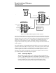
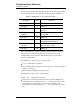
Table Of Contents
- Table of Contents
- List of Figures
- List of Tables
- Foreword
- 1 Introduction
- 1.1 Model 4Q1010PS-430 Integrated Power Supply System Features
- 1.1.1 Digitally-Controlled
- 1.1.2 Superior Resolution and Stability
- 1.1.3 Intuitive Human-Interface Design
- 1.1.4 Flexibility
- 1.1.5 Standard Remote Interfaces
- 1.1.6 Programmable Safety Features
- 1.1.7 Condition-Based Magnet Auto-Rampdown
- 1.1.8 Model 4Q1010PS-430 General Description
- 1.1.9 Power Supply System Rack Front Panel Layout
- 1.2 Model 430 Front Panel Layout
- 1.3 Model 430 Rear Panel Layout
- 1.4 Power Supply Unit Front Panel Layout
- 1.5 System Specifications @ 25 C
- 1.6 Operating Characteristics
- 1.1 Model 4Q1010PS-430 Integrated Power Supply System Features
- 2 Installation
- 3 Operation
- 3.1 System Power On/Off Sequence
- 3.2 Model 430 Programmer Default Display
- 3.3 Entering Numeric Values
- 3.4 Using Fine Adjust Knob to Adjust Numeric Values
- 3.5 Entering Picklist Values
- 3.6 Single-key Commands / Menu
- 3.7 SHIFT-key Commands / Menus
- Figure 3-5. SHIFT-Key Functions
- 3.7.1 Ramp Rate SHIFT-key
- 3.7.2 Voltage Limit SHIFT-key
- 3.7.3 Reset Quench SHIFT-key
- 3.7.4 Increment Field SHIFT-key
- 3.7.5 Field <> Current SHIFT-key
- 3.7.6 Decrement Field SHIFT-key
- 3.7.7 Field Units SHIFT-key
- 3.7.8 Persistent Switch Heater Current SHIFT-key
- 3.7.9 Stability SHIFT-key
- 3.7.10 Vs <> Vm SHIFT-key
- 3.7.11 Volt Meter SHIFT-key
- 3.7.12 Fine Adjust SHIFT-key
- 3.7.13 Persist. Switch Control SHIFT-key
- 3.8 LED Indicators
- 3.9 Setup Menu
- 3.10 Setup Submenu Descriptions
- Figure 3-7. Setup Menu Structure
- 3.10.1 Supply Submenu
- 3.10.2 Load Submenu
- 3.10.2.1 Stability Setting
- 3.10.2.2 Coil Constant
- 3.10.2.3 Magnet Current Rating
- 3.10.2.4 Current Limit
- 3.10.2.5 Calculate Magnet Inductance
- 3.10.2.6 PSwitch Installed
- 3.10.2.7 PSwitch Current Detect (mA)
- 3.10.2.8 PSwitch Current
- 3.10.2.9 PSwitch Heated Time
- 3.10.2.10 PSwitch Cooled Time
- 3.10.2.11 PSwitch Power Supply Ramp Rate
- 3.10.2.12 PSwitch Cooling Gain
- 3.10.2.13 Enable Quench Detect
- 3.10.2.14 Energy Absorber Present
- 3.10.2.15 Enable External Rampdown
- 3.10.3 Misc Submenu
- 3.10.4 Net Settings Submenu
- 3.10.5 Net Setup Submenu
- 3.11 Example Setup
- 3.12 Ramping Functions
- 3.13 Persistent Switch Control
- 3.14 Ramping Functions Example
- 3.15 Quench Detection
- 3.16 External Rampdown
- 3.17 Summary of Operational Limits and Default Settings
- 4 Remote Interface Reference
- 4.1 SCPI Command Summary
- 4.2 Programming Overview
- 4.3 RS-232 Configuration
- 4.4 Ethernet Configuration
- 4.5 Command Reference
- 4.5.1 System-Related Commands
- 4.5.2 Status System Commands
- 4.5.3 SETUP Configuration Commands and Queries
- 4.5.4 Protection Commands and Queries
- 4.5.5 Ramp Configuration Commands and Queries
- 4.5.6 Ramping State Commands and Queries
- 4.5.7 Switch Heater Command and Query
- 4.5.8 Quench State Commands and Queries
- 4.5.9 Rampdown State Queries
- 4.5.10 Trigger Functions
- 4.6 Error Messages
- 5 Service
- 5.1 System Component Maintenance
- 5.2 Troubleshooting Hints
- 5.2.1 Electrostatic Discharge Precautions
- 5.2.2 The Model 430 does not appear to be energized
- 5.2.3 FAILURE TO LOAD message displayed after power-up
- 5.2.4 Power supply unstable - magnet voltage oscillates
- 5.2.5 The power supply system will not charge the magnet.
- 5.2.6 Cannot charge the magnet at the selected ramp rate.
- 5.2.7 Cannot discharge the magnet at the selected ramp rate
- 5.2.8 Cannot charge the magnet to desired field.
- 5.2.9 Current in only one direction from 4-quadrant supply
- 5.2.10 Cannot place the magnet in persistent mode.
- 5.2.11 Cannot bring the magnet out of persistent mode.
- 5.2.12 The magnet quenches for no apparent reason
- 5.2.13 Cannot lower the magnet field
- 5.2.14 There is excessive LHe boil-off during operation.
- 5.2.15 Cannot display the magnetic field strength, only current
- 5.2.16 Cannot use remote communications commands.
- 5.2.17 Magnet current drifts unacceptably while PSwitch cooling
- 5.2.18 Model 430 appears to lock up when connecting to network
- 5.3 Additional Technical Support
- 5.4 Return Authorization
- Appendix
- A.1 Magnet Station Connectors
- A.2 LHe Level / Temp Connectors
- A.3 Programmer Shunt Terminals
- A.4 Program Out Connector
- A.5 Quench I/O Connector
- A.6 Aux Inputs Connector
- A.7 Ethernet Connector
- A.8 RS-232 Connector
- A.9 Abbreviations and Acronyms used in this Manual
- A.10 Model 430 Programmer Specifications
- A.11 Power Supply Details
- A.12 Remote Computer Communication with the Model 430
- A.13 Upgrading the Model 430 Firmware via FTP
- A.14 Upgrading the Model 430 Firmware via Flash Card Reader
- A.15 Model 430 Remote Control Application
- A.16 Model 430IP Power Supply Programmer
- A.17 Persistent Switch Operation Flowchart
- Index

100 Rev. 5
Remote Interface Reference
SCPI Introduction
*ETE <enable_value>
*ETE?
*TRG
4.2 Programming Overview
The Model 430 Programmer conforms to the SCPI (Standard Commands
for Programmable Instruments) IEEE standard. The SCPI standard is an
ASCII-based specification designed to provide a consistent command
structure for instruments from various manufacturers.
The Model 430 Programmer also implements a status system for
monitoring the state of the Model 430 through the Standard Event and
Status Byte registers.
4.2.1 SCPI Language Introduction
SCPI commands conform to a tree structure where commands are grouped
according to common keywords. For example, commands which set a
Model 430 Programmer setup or operating parameter begin with the
keyword CONFigure. The keywords are shown in upper case and lower
case to indicate acceptable abbreviations. For the example keyword
CONFigure, the user may send either the abbreviated form of CONF, or the
entire keyword CONFIGURE. Any other form of the keyword is illegal and
will generate an error.
Many commands also require multiple keywords to traverse the tree
structure of the entire Model 430 Programmer command set. For example,
commands associated with a current setting require the prefix of
CONFigure:CURRent. Note that a colon ( : ) separates the keywords. No
spaces are allowed before or after the colon. Parameters must be separated
from the command keyword(s) by at least one space.
4.2.2 SCPI Status System
The Model 430 Programmer status system reports various conditions of
the instrument in two registers groups shown in Figure 4-1. The register
groups consist of a condition or event register, and an enable register
which controls the actions of specific bits within the condition or event
registers
A condition register continuously monitors the state of the instrument.
The bits of a condition register are updated in real time. A condition
register is read-only and is not cleared when you read the register. A query
of a condition register returns a decimal value in the appropriate output
buffer which corresponds to the binary-weighted sum of all bits set in the
register.