
User guide
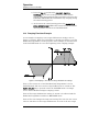

Table Of Contents
- Table of Contents
- List of Figures
- List of Tables
- Foreword
- 1 Introduction
- 1.1 Model 4Q1010PS-430 Integrated Power Supply System Features
- 1.1.1 Digitally-Controlled
- 1.1.2 Superior Resolution and Stability
- 1.1.3 Intuitive Human-Interface Design
- 1.1.4 Flexibility
- 1.1.5 Standard Remote Interfaces
- 1.1.6 Programmable Safety Features
- 1.1.7 Condition-Based Magnet Auto-Rampdown
- 1.1.8 Model 4Q1010PS-430 General Description
- 1.1.9 Power Supply System Rack Front Panel Layout
- 1.2 Model 430 Front Panel Layout
- 1.3 Model 430 Rear Panel Layout
- 1.4 Power Supply Unit Front Panel Layout
- 1.5 System Specifications @ 25 C
- 1.6 Operating Characteristics
- 1.1 Model 4Q1010PS-430 Integrated Power Supply System Features
- 2 Installation
- 3 Operation
- 3.1 System Power On/Off Sequence
- 3.2 Model 430 Programmer Default Display
- 3.3 Entering Numeric Values
- 3.4 Using Fine Adjust Knob to Adjust Numeric Values
- 3.5 Entering Picklist Values
- 3.6 Single-key Commands / Menu
- 3.7 SHIFT-key Commands / Menus
- Figure 3-5. SHIFT-Key Functions
- 3.7.1 Ramp Rate SHIFT-key
- 3.7.2 Voltage Limit SHIFT-key
- 3.7.3 Reset Quench SHIFT-key
- 3.7.4 Increment Field SHIFT-key
- 3.7.5 Field <> Current SHIFT-key
- 3.7.6 Decrement Field SHIFT-key
- 3.7.7 Field Units SHIFT-key
- 3.7.8 Persistent Switch Heater Current SHIFT-key
- 3.7.9 Stability SHIFT-key
- 3.7.10 Vs <> Vm SHIFT-key
- 3.7.11 Volt Meter SHIFT-key
- 3.7.12 Fine Adjust SHIFT-key
- 3.7.13 Persist. Switch Control SHIFT-key
- 3.8 LED Indicators
- 3.9 Setup Menu
- 3.10 Setup Submenu Descriptions
- Figure 3-7. Setup Menu Structure
- 3.10.1 Supply Submenu
- 3.10.2 Load Submenu
- 3.10.2.1 Stability Setting
- 3.10.2.2 Coil Constant
- 3.10.2.3 Magnet Current Rating
- 3.10.2.4 Current Limit
- 3.10.2.5 Calculate Magnet Inductance
- 3.10.2.6 PSwitch Installed
- 3.10.2.7 PSwitch Current Detect (mA)
- 3.10.2.8 PSwitch Current
- 3.10.2.9 PSwitch Heated Time
- 3.10.2.10 PSwitch Cooled Time
- 3.10.2.11 PSwitch Power Supply Ramp Rate
- 3.10.2.12 PSwitch Cooling Gain
- 3.10.2.13 Enable Quench Detect
- 3.10.2.14 Energy Absorber Present
- 3.10.2.15 Enable External Rampdown
- 3.10.3 Misc Submenu
- 3.10.4 Net Settings Submenu
- 3.10.5 Net Setup Submenu
- 3.11 Example Setup
- 3.12 Ramping Functions
- 3.13 Persistent Switch Control
- 3.14 Ramping Functions Example
- 3.15 Quench Detection
- 3.16 External Rampdown
- 3.17 Summary of Operational Limits and Default Settings
- 4 Remote Interface Reference
- 4.1 SCPI Command Summary
- 4.2 Programming Overview
- 4.3 RS-232 Configuration
- 4.4 Ethernet Configuration
- 4.5 Command Reference
- 4.5.1 System-Related Commands
- 4.5.2 Status System Commands
- 4.5.3 SETUP Configuration Commands and Queries
- 4.5.4 Protection Commands and Queries
- 4.5.5 Ramp Configuration Commands and Queries
- 4.5.6 Ramping State Commands and Queries
- 4.5.7 Switch Heater Command and Query
- 4.5.8 Quench State Commands and Queries
- 4.5.9 Rampdown State Queries
- 4.5.10 Trigger Functions
- 4.6 Error Messages
- 5 Service
- 5.1 System Component Maintenance
- 5.2 Troubleshooting Hints
- 5.2.1 Electrostatic Discharge Precautions
- 5.2.2 The Model 430 does not appear to be energized
- 5.2.3 FAILURE TO LOAD message displayed after power-up
- 5.2.4 Power supply unstable - magnet voltage oscillates
- 5.2.5 The power supply system will not charge the magnet.
- 5.2.6 Cannot charge the magnet at the selected ramp rate.
- 5.2.7 Cannot discharge the magnet at the selected ramp rate
- 5.2.8 Cannot charge the magnet to desired field.
- 5.2.9 Current in only one direction from 4-quadrant supply
- 5.2.10 Cannot place the magnet in persistent mode.
- 5.2.11 Cannot bring the magnet out of persistent mode.
- 5.2.12 The magnet quenches for no apparent reason
- 5.2.13 Cannot lower the magnet field
- 5.2.14 There is excessive LHe boil-off during operation.
- 5.2.15 Cannot display the magnetic field strength, only current
- 5.2.16 Cannot use remote communications commands.
- 5.2.17 Magnet current drifts unacceptably while PSwitch cooling
- 5.2.18 Model 430 appears to lock up when connecting to network
- 5.3 Additional Technical Support
- 5.4 Return Authorization
- Appendix
- A.1 Magnet Station Connectors
- A.2 LHe Level / Temp Connectors
- A.3 Programmer Shunt Terminals
- A.4 Program Out Connector
- A.5 Quench I/O Connector
- A.6 Aux Inputs Connector
- A.7 Ethernet Connector
- A.8 RS-232 Connector
- A.9 Abbreviations and Acronyms used in this Manual
- A.10 Model 430 Programmer Specifications
- A.11 Power Supply Details
- A.12 Remote Computer Communication with the Model 430
- A.13 Upgrading the Model 430 Firmware via FTP
- A.14 Upgrading the Model 430 Firmware via Flash Card Reader
- A.15 Model 430 Remote Control Application
- A.16 Model 430IP Power Supply Programmer
- A.17 Persistent Switch Operation Flowchart
- Index

88 Rev. 5
Operation
Quench Detection : Disabling Internal Detection
3.15.2 Disabling Internal Quench Detection
The internal quench detection feature may be disabled in the Load
submenu
1
. However, the rear panel Quench I/O connector output remains
active.
If the internal quench detection feature is disabled, the Model 430
Programmer attempts to limit the error between the commanded current
and the present current to a value that will not result in excessive voltages
being introduced across the magnet terminals. Under most operating
conditions this will not damage any internal protection circuits of the
magnet. If an actual quench condition occurs, the Model 430 will follow the
magnet current to zero unless the user intervenes. If the rear panel
Quench I/O connector is asserted, the Model 430 will force the power
supply output to zero volts regardless of whether the internal quench
detection is enabled or disabled.
In the event that the persistent switch becomes normal without user or
remote activation of the switch heater control, the Model 430 Programmer
will match the magnet current and attempt to stabilize the load if the
internal quench detection feature is disabled. If the internal quench
detection feature is enabled, then this event will generally trigger the
quench detection logic if a difference exists between the magnet current
and the real-time setpoint current of the Model 430.
3.16 External Rampdown
This feature
2
is useful in any application requiring magnet rampdown in
response to an event that can be represented by the closure of a pair of
electrical contacts
3
.
A user input for initiating external rampdown is provided on the rear
panel of the Model 430 Programmer. The process is started by shorting, for
at least 10 milli-seconds, the input connections through closure of user-
supplied external contacts. Once triggered, rampdown of the magnetic
field of the magnet is initiated. Operator intervention (such as Ramp/
Pause, ESC, etc.) is inhibited until rampdown is completed and the
external rampdown signal is cleared.
The external rampdown feature is ideally suited for use with AMI’s Model
135 Liquid Helium Level Monitor. The Model 135 has externally accessible
normally-open relay contacts that close whenever helium level drops below
1. Refer to section 3.10.2.13 on page 57.
2. When enabled. Refer to section 3.10.2.15 on page 58.
3. Refer to section A.5.2 on page 150. The contact closure time must be at least 10
milli-seconds to ensure it doesn’t fall between the sampling points of the Model 430
Programmer.