
User guide

57
Appendix
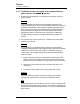
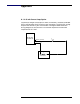
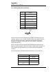
A.1 4-20 mA Current Loop Option
The 4-20 mA output utilizes pins 2 and 4 of connector J8. When the Model
187 is configured for the 4-20 mA current loop option, the 0-10 VDC analog
output from connector J8 is not available. The figure below shows the
wiring diagram for the receiver. The 4-20 mA output has a maximum
compliance of 11.5 VDC.
Receiver
Model 187
Instrument
R
L
I
LOOP
+
_
J8 pin 2 (
I
OUT
)
J8 pin 4 (common)