
User guide

9
Installation
Connecting the sensor cables
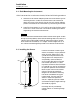
2.4 Connecting the Model 187 to the Sensor
Note
The electrical characteristics of the interconnecting coaxial cables
are temperature dependent over extreme ranges and the cables may
become brittle at cryogenic temperatures. The cables should be
mounted in such a manner as to avoid large temperature gradients
such as those encountered in the path of dewar vents.
Caution
Operation of the AMI Model 187 Liquid Level Instrument with a
device other than an AMI Liquid Level Sensor may void the
instrument warranty.
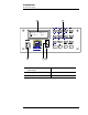
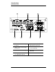
Connect
the Model 187 to the sensor using the six supplied RG-59/U
coaxial cables. Ensure the cables are connected to the correct sensor and
instrument
BNC connecto
r (see Figure 2-1 below and page 5 for a system
diagram). The numbers shown in Figure 2-1 will be metal-stamped on the
sensor top-plate and probe cable adapter.
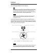
Caution
Moisture or contaminants in any of the BNC coaxial connectors can
short the measurement and cause erroneous readings. A pack of
non-conductive electrical connection lubricant (ECL) has been
2
4
1
5
3 6
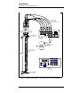
CONNECT TO
CENTER BNC CONNECTOR
CONNECT
1
TO OUTPUTS: GAS REF (J1)
CONNECT
4
TO INPUTS: GAS REF (J4)CONNECT
2
TO OUTPUTS: LIQ REF (J2)
CONNECT
5
TO INPUTS: LIQ REF (J5)
CONNECT
3
TO OUTPUTS: PROBE (J3) CONNECT
6
TO INPUTS: PROBE (J6)
Figure 2-1.
Diagram of sensor top-plate and cable connections.