
Instruction Manual


Rev. 3 71
Index
A
activity LED 29
AMI Internet e-mail address 66
AMI WWW address 66
applicable hardware viii
approximate calibration factor 26
audible alarm 29
C
calibration
approximate calibration 25
closed dewar calibration 21
presetting MAX/MIN 22
calibration methods 19
configuration
A/B setpoints 31
active length 29
controller output mode 32
fill timer 32
HI setpoint 30
LO setpoint 30
units 3 3
connector J2 pinout 68
current loop option 67
D
DB-25 to DB-9 translation 69
dielectrics for common liquids 70
E
ESD precautions 61
external cable shields 67
F
features 1
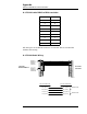
front panel layout 3 , 5
H
HI/LO contacts specs 68
I
IEEE-488 communications
commands 46
communication flow 42
device clear 46
DIP switch 44
error codes 50
primary address 44
remote calibration 49
spoll byte 49
terminators 4 2
input voltage configuration 15
installation
rack mounting 12
M
method of measurement 17
R
rack mounting 12
rear panel layout 4, 6
return authorization 66
S
safety
equipment x
legend x
sensor connection 13
sensor contamination 34
sensor installation 12
serial communications
baud rate 36
commands 38
data logger 37
DIP switch 36
echo function 36
interactive communication 35
remote calibration 41
terminators 3 5
serial port connector/cables 35
specifications 8
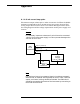
system diagram 7
T
troubleshooting
checking communications setup 64
contacting AMI support 66
erratic display 64
instrument responds with -8 65
no controller output 64
no level reading 62
power LED off 62
replacing the fuse 62
U
unpacking 1 1
V
virtual instruments
description 51
IEEE-488 initialization 56
IEEE-488 llb files 55
illustration 51
requirements 51
RS-232 initialization 53
RS-232 llb file 52
running multiple GPIB devices 58
running the IEEE-488 vi 57
running the RS-232 vi 54