
Instruction Manual

44 Rev. 3
Remote Interface Reference
IEEE-488 Communication DIP Switch Settings
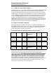
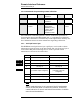
5.2.3 IEEE-488 Communication DIP Switch Settings
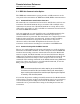
The 5 DIP switches located on the rear panel of the Model 185/186 are
used to set the primary IEEE-488 bus address of the unit.
5.2.3.1 IEEE-488 primary bus address
The Model 185/186 primary bus address is controlled by switches 1
through 5 of the communication DIP switch on the rear panel. Valid
primary addresses are between 0 and 30. The Model 185/186 does not use
secondary addressing. Note that many IEEE-488 controller cards in
external computers will use address 0 (or 21). The bus address for each
Model 185/186 should be unique with respect to other Model 185/186 units
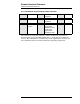
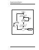
or any other devices on the bus. The switch settings for the various
addresses are (on = 1 or the up position):
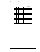
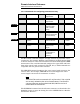
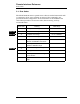
DIP switch Primary bus
address
12345
off off off off off 0
off off off off on 1
off off off on off 2
off off off on on 3
off off on off off 4
off off on off on 5
off off on on off 6
off off on on on 7
off on off off off 8
off on off off on 9
off on off on off 10
off on off on on 11
off on on off off 12
off on on off on 13
offonononoff 14
offonononon 15
on off off off off 16
on off off off on 17
on off off on off 18
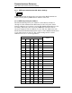
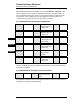
1
0
12345
ON