
Instruction Manual

Rev. 3 37
Remote Interface Reference
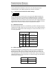
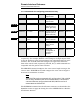
Serial Communication DIP Switch Settings
5.1.3.3 Data logger function
Switch 1 of the communications DIP switch controls the data logger
function. The unit is shipped with the data logger function disabled. This
feature is normally used with a printer rather than a host computer, since
a computer can be more usefully programmed utilizing the available
command set. The data logger function generates a time relative to
instrument power-up and a corresponding level. The units of the level
output are set by the units mode toggle switch. The time and
corresponding level are formatted and output to the host device at regular
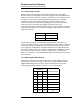
intervals as specified by the switches 3 through 5. The settings for the data
logger function are:
The host device can be a standard dot matrix printer connected via a
serial-to-parallel converter, or connected directly with a printer capable of
receiving serial data. Presumably, any serial-to-parallel converter which
can be properly configured is acceptable. AMI has tested the Model 185/
186 with a standard, low cost converter configured as a DTE device, 8 data
bits, no parity, and 1 stop bit. In order to communicate with the host
device, it is necessary to set the Model 185/186 to the identical baud rate of
the host device.
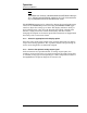
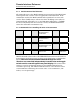
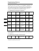
5.1.3.4 Data logger output interval
The interval between successive output from the data logger function is
controlled by switches 3 through 5. The unit is shipped with the data
logger function disabled (see above). The available intervals and the
corresponding switch settings are (on = 1 or the up position):
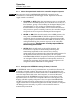
DIP switch 1 Function
on Data Logger On
off Data Logger Off
DIP switch
Interval (minutes)345
off off off 1
off off on 2
off on off 5
off on on 10
on off off 20
on off on 30
on on off 60