
Instruction Manual


Rev. 3 5
Introduction
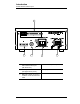
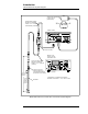
Model 186 Front Panel Layout
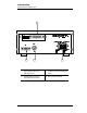
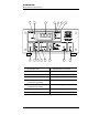
1.4 Model 186 Front Panel Layout
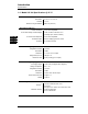
1 Fill indication LED 9 MIN calibration push-button
2 Activity LED 10 Approximate calibration push-button
3 LED display 11 MAX calibration push-button
4 HI level LED 12 Fill toggle switch
5 A level LED
(control band upper limit)
13 Control mode rotary switch
6 B level LED
(control band lower limit)
14 Raise/lower toggle switch
7 LO level LED 15 Units mode toggle switch
8 Power toggle switch
$0,
}
a
2
O
4
8
9 10 11 13 14 1512
5
7
6
2
3
1
100.0