EXCELLENCE IN MAGNETICS AND CRYOGENICS MODEL 185/186 LIQUID LEVEL INSTRUMENT INSTALLATION, OPERATION, AND MAINTENANCE INSTRUCTIONS American Magnetics, Inc. PO Box 2509, 112 Flint Road, Oak Ridge, TN 37831-2509, Tel: 865 482-1056, Fax: 865 482-5472 Rev.
Declaration of Conformity Application of Council Directives: Low Voltage Directive 72/23/EEC EMC Directive 89/336/EEC Manufacturer’s Name: American Magnetics, Inc. Manufacturer’s Address: 112 Flint Road, P.O. Box 2509 Oak Ridge, TN 37831-2509 U.S.A.
Table of Contents 1 2 3 4 Rev. 3 Introduction .............................................................................. 1 1.1 Model 185/186 Features............................................................ 1 1.2 Model 185 Front Panel.............................................................. 3 1.3 Model 185 Rear Panel ............................................................... 4 1.4 Model 186 Front Panel Layout ................................................ 5 1.
Table of Contents 5 6 7 Remote Interface Reference ..................................................35 5.1 Serial Communication/Data Logger Option ...........................35 5.1.1 Serial port connector and cabling................................35 5.1.2 Command/return termination characters...................35 5.1.3 Serial Communication DIP Switch Settings...............36 5.1.4 Serial Command Set Reference ...................................38 5.2 IEEE-488 Communication Option ..................
Foreword Purpose and Scope This manual contains the operation and maintenance instructions for the American Magnetics, Inc. Model 185/186 Liquid Level Instrument. The manual outlines the instructions for instrument use in various system designs.
Foreword Applicable Hardware Applicable Hardware The Model 185/186 has been designed to operate with an AMI Liquid Level Sensor. Operation with other equipment is not recommended and may void the warranty. General Precautions Cryogen Safety Personnel handling cryogenic liquids should be thoroughly instructed and trained as to the nature of the liquids. Training is essential to minimize accidental spilling.
Foreword Safety Summary 2. Do not apply heat. Loosen any clothing that may restrict circulation. Apply a sterile protective dressing to the affected area. 3. If the skin is blistered or there is any chance that the eyes have been affected, get the patient immediately to a physician for treatment. Containers of cryogenic liquids are self pressurizing (as the liquid boils off, vapor pressure increases). Hoses or lines used to transfer these liquids should never be sealed at both ends (i.e.
Foreword Safety/Manual Legend rupture disks, etc.) included in the cryostat and top plate assembly are necessary. Recommended Safety Equipment First Aid kit Fire extinguisher rated for class C fires Leather gloves Face shield Signs to indicate that there are potentially dangerous cryogens in use in the area.
1 Introduction 1.1 Model 185/186 Features The American Magnetics, Inc. (AMI) Model 186 Liquid Level Controller system is an advanced, microprocessor-based solution designed to provide accurate and reliable level monitoring and control of virtually any cryogenic liquid. 1.1.1 Capacitance-based level sensing The system consists of a Model 185/186 Liquid Level Instrument, sensor, connecting cables, and an optional solenoid-operated fill valve. The instrument sensing element is typically a 3/8 inch (9.
Introduction The length adjustment only affects the scaling of the level display and does not change the actual calibration of the instrument. 1.1.5 Microprocessor-based electronics Microprocessor-based electronics provide 0.1% readout accuracy. Nonvolatile memory maintains instrument calibration without battery backup. Watchdog timer circuitry and low line voltage (brownout) detector prevent microprocessor lockup and provide fail-safe operation. 1.1.
Introduction Model 185 Front Panel Layout 1.2 Model 185 Front Panel 1 2 4 3 $&7,9,7< $0, +, /(9(/ 100.
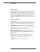
Introduction Model 185 Rear Panel Layout 1.3 Model 185 Rear Panel 1 RS-232 ON $0(5,&$1 0$*1(7,&6 ,1& 2$. 5,'*( 71 8 6 $ S11 J8 &20081,&$7,216 /,1( +] 9$ 0$; - - 2 4 3 9 9 9 9 4 1 Optional RS-232/422 or IEEE488 communications port (RS-232 shown) 3 RG-59/U coaxial connector to oscillator unit via the extension cable 2 Auxiliary DB-9 connector (see Appendix for pinout) 4 Input power connector Rev.
Introduction Model 186 Front Panel Layout 1.4 Model 186 Front Panel Layout 1 2 3 5 4 $&7,9,7< 7 6 $0, +, /(9(/ $ 100.
Introduction Model 186 Rear Panel Layout 1.5 Model 186 Rear Panel Layout 1 RS-232 ON $0(5,&$1 0$*1(7,&6 ,1& 2$.
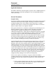
Introduction Instrument/Sensor System Diagram SOLENOID-OPERATED FLOW VALVE (OPTIONAL) EXTENSION CABLE RG-59/U COAXIAL CABLE, 6 FT. LENGTH STANDARD (VARIABLE) REAR PANEL ON RS-232 S11 J8 $0(5,&$1 0$*1(7,&6 ,1& 2$. 5,'*( 71 8 6 $ &20081,&$7,216 &21752//(5 287387 /,1( +] $ 0$; - - /,1( 92/7$*( $ 0$; 9 9 9 9 OSCILLATOR MODEL 186 LIQUID LEVEL CONTROLLER OSCILLATOR CABLE RG-59/U COAXIAL CABLE, 6 FT. LENGTH (FIXED) TOTAL SENSOR LENGTH 12-255.
Introduction Specifications 1.6 Model 185/186 Specifications @ 25 °C Level Measurementsa Resolution: Linearity: Maximum Length Readout: 0.1%, 0.1 cm, or 0.1 in ± 0.1% 650.0 cm (255.9 in) Operating Parameters HI and LO Alarms: HI/LO Alarm Relay Contact Ratings: 0RGHO A and B Control Setpoints: 0RGHO Controller Output: 0RGHO Fill Timer: 0% to 100% adjustable 10 VA, 30 VAC or 60 VDC, 0.5 A (normally open, closed on alarm) 0% to 100% adjustable AC line voltage @ 2A max current 0.1 to 600.
Introduction Specifications Physical Dimensions (Standard): Weight (Standard): Dimensions (Rack Mount): 97 mm H x 213 mm W x 282 mm D (3.8" H x 8.4" W x 11.1" D) 1.6 kg (3.6 lbs.) 89 mm H x 483 mm W x 282 mm D (3.5" H x 19" W x 11.1" D) Weight (Rack Mount): 2.0 kg (4.3 lbs.) Ambient Temperature: Operating: 0 °C to 50 °C (32 °F to 122 °F) Nonoperating: −20 °C to 60 °C (−4 °F to 140 °F) Environmental Relative Humidity: 0 to 95%; non-condensing a.
Introduction Specifications 10 Rev.
2 Installation Warning Before energizing the instrument, the earth ground of the power receptacle must be verified to be at earth potential and able to carry the rated current of the power circuit. Using extension cords should be avoided; however, if one must be used, ensure the ground conductor is intact and capable of carrying the rated current.
Installation Installing the sensor 2.2 Rack Mounting the Instrument If the instrument has a rack mount chassis, follow the following procedure: a. Attach the rack mount adapter pieces to the instrument by first removing the four screws on the side of the instrument that attach the cover to the chassis. Attach the rack mount adapter pieces to the sides of the instrument by reinstalling the screws. b.
Installation Interconnects with oscillator and valve 2.4 Connecting the Oscillator Cable to the AMI Sensor Connect the oscillator to the sensor using a supplied 6 foot RG-59/U coaxial cable. Ensure the oscillator is connected in the correct orientation (see page 7 for a system diagram). The cable length between the oscillator and the sensor should not exceed 6 feet unless longer lengths were discussed with an Authorized AMI Technical Representative.
Installation Interconnects with oscillator and valve 2.6 Installing an Optional Solenoid-operated Fill Valve 0RGHO Install a solenoid-operated fill valve by connecting the valve power cable to the AC controller output receptacle on the rear panel of the instrument. The standard AMI supplied valve has a 9/32 inch orifice and the input and output are tapped for 3/8 NPT. Operation of the controller output receptacle in AUTO mode should be avoided until the instrument setpoints have been specified.
Installation Verifying power requirements 2.7 Connecting the Instrument to Power Warning The Model 185/186 operates on 50-60 Hz power and may be configured for 110-120 or 208-240 VAC ±10% (100 or 200 VAC ±10% for Japan and South Korea). The power requirements for each instrument is marked on the calibration sticker on the bottom of the instrument. Be sure your instrument is configured for your power source prior to plugging in the line cord.
Installation Verifying power requirements 16 Rev.
3 Calibration Model 185/186 instruments are calibrated at the factory for a specific length sensor for use in a specific liquid. The calibration length and calibration liquid are listed on the calibration sticker on the bottom of the instrument. If the factory calibration method utilized was approximate, the calibration length will be noted as an approximate value. 3.
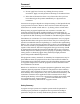
Calibration Effects of dieletric shifts Diel-1 (saturated liquid) 0.5 Diel-1 (saturated vapor) 0.45 0.4 0.35 Diel - 1 0.3 0.25 0.2 0.15 0.1 0.05 0 0 50 100 150 200 250 300 350 400 450 500 Pressure (psi) Figure 3-1. Dielectric vs. pressure for nitrogen under saturated conditions. To minimize the effects of shifts in the dielectric of the target liquid, perform a closed dewar calibration (see page 21) at the expected operating condition of the cryo-vessel.
Calibration Calibration methods 3.3 Calibration Methods for Model 185/186 Instruments The most straightforward calibration method is the Open Dewar Calibration which requires the customer to have access to a filled dewar where the full active length of the sensor can be dipped. The Closed Dewar Calibration method can be performed in situations where it is not feasible for the customer to dip the sensor into an open dewar, such as situations where the target liquid is under pressure.
Calibration Calibration methods START Instrument & sensor purchased together? Y Verify sensor specifications Verify calibration sticker on bottom of instrument Is factory calibration correct? Y N N Can Open Dewar Calibration be performed in target liquid? Y Can Open Dewar Calibration be performed in target liquid? Y** Is factory calibration Approximate? N Y N Perform Open Dewar Calibration N Can Closed Dewar Calibration be performed in target liquid? Y Y Can Closed Dewar Calibration be
Calibration Open dewar calibration 3.3.1 Open dewar calibration The instrument should be energized with the sensor connected to the instrument via the oscillator (see the system diagram on page 7). 1. Slowly insert the sensor into the liquid until the level rests approximately one inch below the top sensor hole and then press the MAX push-button through the small hole provided on the instrument front panel. When the calibration point has been accepted, the display will show "bbb.
Calibration Closed dewar calibration 3.3.2.1 Presetting the MAX/MIN calibration points The following procedure should be performed before installation of the sensor in the target cryo-vessel. 1. Connect the extension and oscillator cables to the J5 coaxial connector on the rear panel of the instrument (see page 7 for a system diagram). Do not connect the sensor. Energize the instrument. Press the MIN push-button through the small hole provided on the instrument front panel.
Calibration Closed dewar calibration 3.3.2.2 Completing the closed dewar calibration procedure 1. Install the sensor in the dewar and energize the instrument with the sensor connected to the instrument via the oscillator and extension cables (see the system diagram on page 7). 2. Set the LENGTH to the active length of the sensor. After setting the LENGTH, set the units mode toggle switch to the % setting. For details on setting the LENGTH and units mode, refer to the Operation section of this manual. 3.
Calibration Closed dewar calibration should decrease significantly when the liquid reaches the hole in the top of the sensor. When the break in the slope of the level trace occurs (i.e. the slope of the level trace becomes 0 or horizontal), push the MAX pushbutton through the small hole provided in the instrument front panel. When the calibration data has been accepted, the display will show "bbb.b" and the push-button can then be released.
Calibration Approximate calibration calibrated with a standard active region of 20". The LENGTH setting of the instrument should also be configured for 20". 7. Proceed to the Operation section for directions for configuring the instrument. 3.3.3 Approximate calibration This procedure is the least accurate form of calibration and should be used only when the aforementioned calibration procedures are not viable.
Calibration Approximate calibration 4. Measure the distance between the bottom hole of the sensor and the location of the liquid level noted during step 3. This measured length is Ldipped. 5. The dielectric constant for the reference liquid, e1, and the target liquid, e2, must be known to complete the approximate calibration.
Calibration Approximate calibration Note The last approximate calibration factor is not retained in the instrument memory, therefore the effects of repeated approximate calibrations are cumulative. Example: Purchased a 100" active length sensor for operation in liquid argon at atmospheric pressure, however only liquid nitrogen is available for calibration at a maximum depth of 30": First, the sensor is dipped as far as possible into the liquid nitrogen and cooled.
Calibration Approximate calibration 28 Rev.
4 Operation The Model 185/186 and sensor (if applicable) were functionally tested and calibrated at the factory. The calibration sticker located on the bottom of the instrument shows the calibration length, calibration liquid, and whether an approximate calibration method was utilized at the factory. In the event that the calibration is incorrect for the application, the instrument will need to be recalibrated by the user with a specific sensor and liquid.
Operation HI/LO setpoints physical distance between the locations of the MIN and MAX calibration points on the sensor is the active length. The instrument allows the user to display the liquid level in units of length (inches or centimeters) in addition to a percentage. The instrument was shipped with the length value set to the active sensor length if a sensor was purchased with the instrument. To view the present length setting, place the units mode toggle switch in either the INCH or CM position.
Operation A/B setpoints or exceeds the LO setpoint, the LED is extinguished and the contacts open. Note The HI and LO contacts are both closed on power-off of the instrument which is a state unique to the power-off condition. Note If the LENGTH is adjusted subsequent to configuring the various setpoints, the percentage of active length will be maintained for all setpoints.
Operation Controller output modes 4.1.5 0RGHO Select the operational mode of the controller output receptacle The operation of the CONTROLLER OUTPUT receptacle of the instrument is controlled by the fill toggle switch. Operation of the fill toggle switch is as follows: a.
Operation Fill timer (INTERVAL) Note The INTERVAL function is disabled when the INTERVAL setting is “0.0”. Adjusting the INTERVAL setting to “0.0” will also terminate any in-progress functions of the INTERVAL timer. The INTERVAL setting can be adjusted by placing the control mode rotary switch in the INTERVAL position and using the RAISE/LOWER toggle switch to adjust the setting up or down. The display will move slowly at first and then faster.
Operation Sensor contamination 4.2 Sensor Contamination To ensure proper instrument calibration and operation, care must be taken to ensure the sensor is kept free of contaminants and not subjected to any force which would physically distort the sensor. Water or other electrically conducting substances in the sensor will disturb the measured capacitance and therefore instrument response.
5 Remote Interface Reference 5.1 Serial Communication/Data Logger Option The serial communication/data logger option provides a 25-pin D-type connector on the rear panel of the instrument for serial communications and data logger function. 5.1.1 Serial port connector and cabling An IBM-compatible computer’s serial port can be directly connected to the Model 185/186 via a standard PC modem cable.
Remote Interface Reference Serial Communication DIP Switch Settings of only termination characters. Otherwise, the shared input/output command buffer of the Model 185/186 may become corrupted. 5.1.3 ON Serial Communication DIP Switch Settings 1 1234567 8 0 The 8 DIP switches located on the rear panel of the Model 185/186 are used to control various parameters of the RS-232 interface. Switches 6 through 8 control the baud rate of the interface.
Remote Interface Reference Serial Communication DIP Switch Settings 5.1.3.3 Data logger function Switch 1 of the communications DIP switch controls the data logger function. The unit is shipped with the data logger function disabled. This feature is normally used with a printer rather than a host computer, since a computer can be more usefully programmed utilizing the available command set. The data logger function generates a time relative to instrument power-up and a corresponding level.
Remote Interface Reference Serial Command Set Reference 5.1.4 Serial Command Set Reference All commands sent to the Model 185/186 are processed and the Model 185/ 186 responds with a return value (if applicable) and termination. If the command is invalid, the Model 185/186 will respond with an error code (see the Error Codes section). All return values including error codes are terminated with (i.e. a carriage return followed by a linefeed).
Remote Interface Reference Serial Command Set Reference 5.1.4.
Remote Interface Reference Serial Command Set Reference The SAVE command saves the HI, LO, A, B, INTERVAL, LENGTH, and current remote units settings to permanent memory. Saved settings are then recalled each time the power is turned off and then reapplied to the instrument. If the configuration is changed from the front panel, the settings are automatically saved to permanent memory. 5.1.4.
Remote Interface Reference Serial Command Set Reference 5.1.4.
Remote Interface Reference IEEE-488 Communication Option 5.2 IEEE-488 Communication Option The IEEE-488 communication option provides a GPIB connector on the rear panel of the instrument for IEEE-488 (GPIB, HPIB) communications. 5.2.1 Command/return termination characters All commands are transmitted and received as ASCII values and are case insensitive. The Model 185/186 always transmits and EOI as the termination for return data.
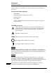
Remote Interface Reference Communicating with the Model 186 Begin Send Command SRQ Asserted? Y N Another Command? Read or Wait for SRQ N Y Get Response End N Y Error? Error Routine Basic communication flow diagram for IEEE-488 commands. Rev.
Remote Interface Reference IEEE-488 Communication DIP Switch Settings 5.2.3 ON IEEE-488 Communication DIP Switch Settings 1 12345 0 The 5 DIP switches located on the rear panel of the Model 185/186 are used to set the primary IEEE-488 bus address of the unit. 5.2.3.1 IEEE-488 primary bus address The Model 185/186 primary bus address is controlled by switches 1 through 5 of the communication DIP switch on the rear panel. Valid primary addresses are between 0 and 30.
Remote Interface Reference IEEE-488 Communication DIP Switch Settings DIP switch Rev.
Remote Interface Reference IEEE-488 Command Set Reference 5.2.4 IEEE-488 Command Set Reference All commands sent to the Model 185/186 are processed and the Model 185/ 186 responds with a return value and termination. If the command is invalid, the Model 185/186 will respond with an error code (see the Error Codes section). All return values including error codes are terminated with (linefeed) and EOI asserted.
Remote Interface Reference IEEE-488 Command Set Reference 5.2.4.
Remote Interface Reference IEEE-488 Command Set Reference The SAVE command saves the HI, LO, A, B, INTERVAL, LENGTH, and current remote units settings to permanent memory. Saved settings are then recalled each time the power is turned off and then reapplied to the instrument. If the configuration is changed from the front panel, the settings are automatically saved to permanent memory. 5.2.4.
Remote Interface Reference Serial Poll Status Byte 5.2.4.
Remote Interface Reference Error Codes 5.3 Error Codes The Model 185/186 returns specific error codes for invalid commands and/ or arguments. If an error condition is returned, the command is not processed and the configuration of the instrument is not modified. The table below provides a list of error codes, their meaning, and any associated limits.
6 Virtual Instrument Operation In order to make the communications options easier to use for the customer, AMI provides a LabVIEW-based interface for remote monitoring and control of the Model 185/186. LabVIEW® is a virtual instrument (VI) development and deployment software tool produced and marketed by National Instruments. LabVIEW is available on several platforms including Microsoft Windows™, Microsoft Windows NT™, Apple Macintosh™, Sun Solaris™, and HP-UX™.
Virtual Instrument Operation RS-232 Virtual Instrument from the VI should be normally be set by using the VI and not the front panel of the instrument. 6.1.1 Launching and initializing the RS-232 VI First, make sure the Model 185/186 is connected to a COM port on the host computer and that the instrument is powered on. The VI library, provided in the file MODEL18X.LLB, for the RS-232 virtual instrument contains the following files: VI Function 18X Alarms.vi Manages alarm functions for 185/186.
Virtual Instrument Operation RS-232 Virtual Instrument VI 0RGHO Function Set 186 Fill via Serial Port.vi Configures the fill interval setting. Set 18X HI via Serial Port.vi Configures the HI setpoint. Set 18X Length via Serial Port.vi Configures the active sensor length. Set 18X LO via Serial Port.vi Configures the LO setpoint. Open the Model 18X via Serial Port.vi. Before running the VI, the user must select an initialization option and provide any necessary settings.
Virtual Instrument Operation RS-232 Virtual Instrument 6.1.2 Interacting with the running VI While the VI is running the user may manipulate the virtual toggle and rotary switches in the same manner as required for the front panel operation of the actual instrument. See the Operation section of this manual for instructions on operating the front panel controls, however, please note that there are some minor differences discussed below. The RAISE/LOWER toggle switch functions slightly different in the VI.
Virtual Instrument Operation IEEE-488 Virtual Instrument 6.2 IEEE-488 Virtual Instrument The IEEE-488 (or GPIB) VI functions nearly identically to the RS-232 VI with a few exceptions. The VI library, provided in the file MODEL18X.LLB, for the IEEE-488 virtual instrument contains the following files: VI Function 18X Alarms.vi Manages alarm functions for 185/186. Config 18X via GPIB.vi Initializes actual instrument from VI configuration. Convert from CM.
Virtual Instrument Operation IEEE-488 Virtual Instrument with multiple devices on one GPIB bus. The exact design of the nonexclusive operation is dependent upon the specific devices you may have connected to the bus. When running a VI it is important to operate the instrument using the VI and not via the actual instrument front panel. Otherwise, the VI and the actual instrument may not be synchronized.
Virtual Instrument Operation IEEE-488 Virtual Instrument primary address (see page 44 for instructions on setting the Model 185/186 primary address). If only one GPIB interface is present in the host computer, the GPIB bus is normally set to 0. Refer to your LabVIEW documentation for more information on how to determine the GPIB bus setting appropriate for your computer. After setting the initialization parameters, the user may then start the VI.
Virtual Instrument Operation Running multiple GPIB devices 6.2.3 Running multiple GPIB devices The Model 18X via GPIB.vi in the MODEL18X.LLB library is designed to have exclusive control of the GPIB bus. AMI recognizes this is generally not the case for a GPIB bus configuration. Therefore, the Non-exclusive loop control.vi example is provided in the COMP18X.LLB library to demonstrate how the Model 18X via GPIB.vi can be cooperatively executed on a GPIB bus with multiple devices connected.
Virtual Instrument Operation Running multiple GPIB devices Rev.
Virtual Instrument Operation Running multiple GPIB devices 60 Rev.
7 Service Guide The procedures in this section should only be performed by Qualified Service Personnel (QSP). 7.1 Troubleshooting Procedures The following paragraphs serve as an aid to assist QSP in troubleshooting a potential problem with the Model 185/186. If the QSP is not comfortable with troubleshooting the system, you may contact an Authorized AMI Technical Support Representative for assistance. Refer to “Additional Technical Support” on page 66.
Service Guide No level reading 7.1.1 No level reading 1. Ensure that the instrument is energized from a power source of proper voltage. Warning If the instrument has been found to have been connected to an incorrect power source, return the instrument to AMI for evaluation to determine the extent of the damage. Frequently, damage of this kind is not visible and must be determined using test equipment.
Service Guide Erratic or erroneous level reading selector requires removal of the top cover of the instrument. Observe the same safety procedures as presented in step 2. 7.1.2 Erratic or erroneous level reading 1. Verify that the sensor is properly connected to the oscillator cable and the extension cable (see the system diagram on page 7). 2. Verify the cabling has no breaks or cuts. 3.
Service Guide Unit not responding to communications 7. Verify the sensor is free of contaminants and not subject to any physical distortion. Disconnect the BNC connector at the top of the sensor and measure the sensor resistance by placing an ohmmeter across the center pin and the outer barrel of the connector. The resistance of the sensor should typically be >10 MΩ. 7.1.
Service Guide Custom Instrument Configurations 488 option, check the primary address setting and make sure the controller software is set to query the instrument at the primary address selected. 3. Check your host communications software and make sure it is recognizing the return termination characters from the instrument. For serial communication, the return termination characters are . For IEEE-488, the return message termination characters are with EOI. 4.
Service Guide Return Authorization VAC ±10% for Japan and South Korea). The power requirements for each instrument are marked on the rear panel. Be sure the instrument’s power requirements match your power source prior to plugging in the line cord. Do not fail to connect the input ground terminal securely to an external earth ground. If the instrument operating voltage needs to be changed, ensure the instrument is de-energized by disconnecting the power cord from the power source.
Appendix A.1 4-20 mA current loop option The 4-20 mA output utilizes pins 1 and 2 of connector J2. When the Model 185/186 is configured for the 4-20 mA current loop option, the 0-10 VDC analog output from connector J2 is not available. The figure below shows the wiring diagram and the voltage requirements for the power supply and receiver.
Appendix Auxiliary connector J2 pinout A.2 Auxiliary connector J2 pinout Pin Function 1 4-20 mA current loop power supply + (optional feature) 2 4-20 mA current loop output (optional feature) 3 0-10 VDC output (optional feature) 4 0-10 VDC common, or 4-20 mA current loop power supply common (optional feature) 5&6 Lo level relay contacts (dry) 7&8 Hi level relay contacts (dry) 9 Not used Pin 1 J2 The HI level and LO level contacts are provided for external use by the customer.
Appendix RS-232 cable DB-25 to DB-9 translation A.3 RS-232 cable DB-25 to DB-9 translation DB-25 Pin DB-9 Pin 2 3 3 2 4 7 5 8 6 6 7 5 8 1 20 4 22 9 All other pins on the DB-25 connector are unused. This is standard PC modem cable wiring. A.
Appendix Dielectric constants for common liquids A.5 Dielectric constants for common liquids The table below contains relative dielectric constants for several common liquids at atmospheric pressure (unless otherwise noted). Liquid Dielectric constanta Argon (A) 1.53 @ −191°C Carbon dioxide (CO2) 1.60 @ 20°C, 50 atm Hydrogen (H2) 1.228 @ 20.4 K Methane (CH4) 1.70 @ −173°C Nitrogen (N2) 1.454 @ −203°C Propane (C3H8) 1.61 @ 0°C Oxygen (O2) 1.507 @ −193°C a. Reference: Weast, Robert C. Ph.D.
Index A R activity LED 29 AMI Internet e-mail address 66 AMI WWW address 66 applicable hardware viii approximate calibration factor 26 audible alarm 29 rack mounting 12 rear panel layout 4, 6 return authorization 66 S calibration approximate calibration 25 closed dewar calibration 21 presetting MAX/MIN 22 calibration methods 19 configuration A/B setpoints 31 active length 29 controller output mode 32 fill timer 32 HI setpoint 30 LO setpoint 30 units 3 3 connector J2 pinout 68 current loop option 67 sa
Index 72 Rev.